STEP ONE: ISOLATING THE PR
OBLEM
NOTE: Before addressing any specific
problem the unit may have, it is advisable to help
isolate the nature of the problem by running a
general check of the 1) Gas Supply and 2)
Electrical Supply. The following procedure will
narrow the possibilities and help direct you to
the source of the problem. A detailed
Troubleshooting section with specific symptoms
and likely corrective courses of action follows
each sub-assembly Partlist section.
CHECK GAS SUPPLY
First, check to see if the gas has been tur ned on.
Next, gain access to the regulator by remov-
ing the grates over the cooktop burners on the far
left hand side of the cooktop. Beneath the grates,
to wards the rear of the burner box, the regulator is
loca ted between the manifold and rear incoming gas
line. Check the top of the regulator to see that it is set
up for the type of gas supplied to the unit. The cap
on top of the regulator indicates whether the unit is
set up for NATURAL or L.P. gas.
When the gas supply is on, check the gas
pr essur e with a manometer. The front main open top
burner orifice is the most convenient place to check
gas pressure. T o access the main burner orifice,
remove the four (4) screws that hold the bur ner
hanger do wn and A) move aside the bur ner assembly
or B) disconnect the igniter wires and remove the
entire burner / hanger assemb ly. Hook up a flexible
line to the main burner orifice, turn that burner on...
the pressur e should read 5.0" W.C. for Natural Gas,
and 10.0" W.C. for L.P. Gas. Turn on other bur ners
and check f or an excessive drop in pressur e. A large
dr op in pr essur e indicates a gas supply pr ob lem relat-
ed to installation, not covered by service warranty.
CHECK ELECTRICAL SUPPLY
First, check to see if the electricity has been turned on.
Next, check power to the cord in the back of
the rang e and at the wall r eceptacle. If power is OK
ther e, the next area to check will be at the service dis-
connect located behind the valve panel. The Valve
Panel can be removed by removing the five (5) scr ews
that hold it in place. Two (2) scr ews ar e located at
each end of the panel, while one (1) screw (painted
Red) behind a Burner Control knob must also be
removed before the valve panel can be removed.
Once the Valve Panel has been removed, unplug and
check for power to the female side of the plug.
Between 110 & 120 volts should be present, if not,
ther e is a prob lem with the cord.
Check for power at the Terminal Blocks,
(Black= Live, White = Neutral)
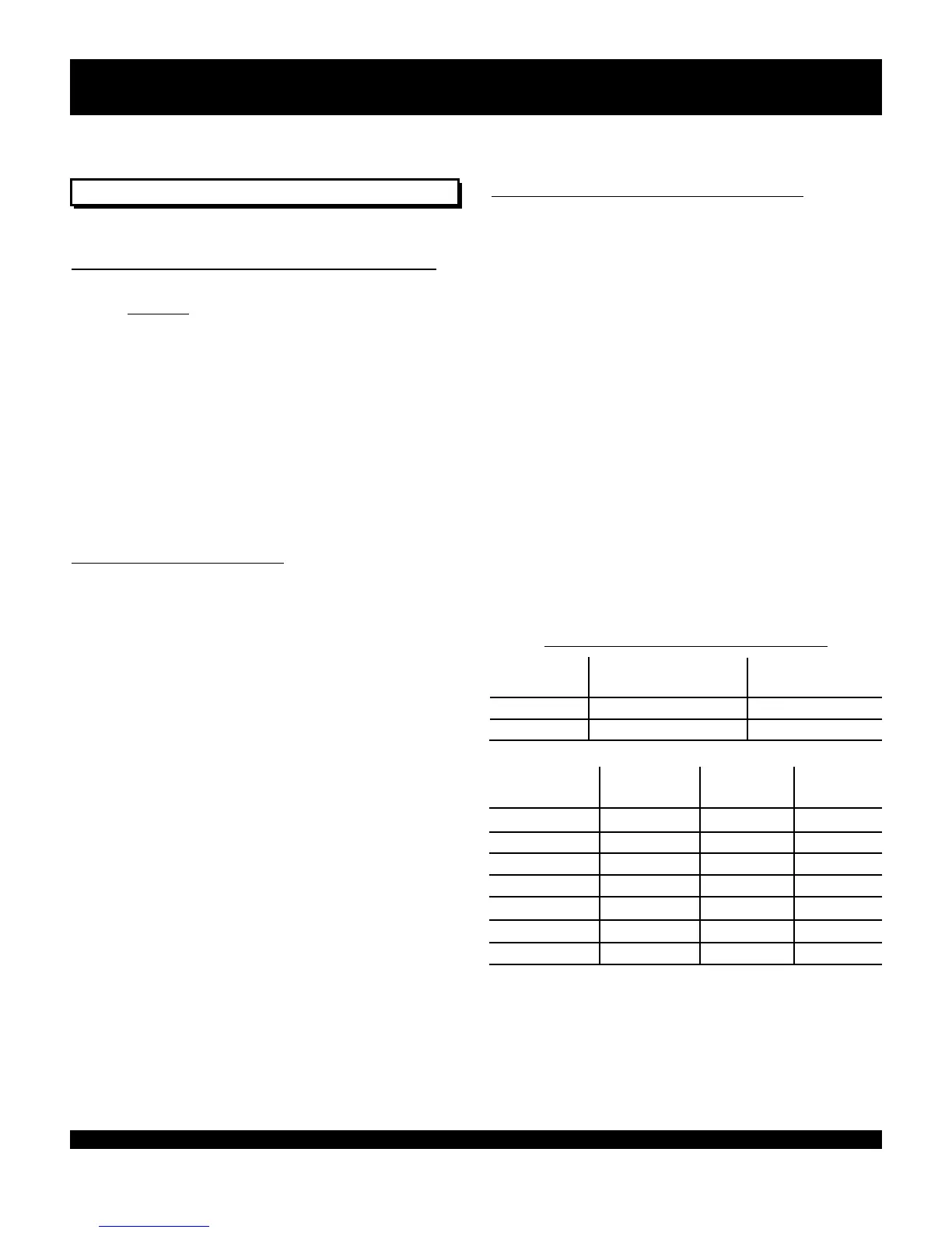
ORIFICE or PIN SIZE R
eferences:
Gas Type Incoming Pressure Pressur e Regulator
to Regulator Supplies
NATURAL 7.0" to 9.0" W.C. 5.0" W.C.
L.P. 11" to 14.0" W.C. 10.0" W.C.
Orifice Size Pin Size Orifice
Size Nat. (DMS) LP (DMS) LP (DMS)
Open Top 51 57 50
Center Simmer 78 87 80
Grill 48 55 55
Griddle 48 55 55
Infra Red Broiler 47 55 55
Small Oven 48 55 55
Large Oven 38 52 52
*NOTE: Ensure the Air Shutter is installed when converting
an I/R Broiler to L.P,. See Gas Hookup Section, Range
Installation Manual.
GENERAL INSTRUCTIONS:
3
INTRODUCTION
 Loading...