5
3
6
4
L
R
L
R
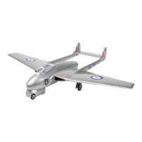
Drill two 2mm holes on where control horn will be
mounted as shown in picture.
Then put 2x12/16/20mm screws through control horn,
flap and aileron (as shown in picture). Then add the
horn base at the underside of flap and aileron, and
lock it in place. Then connect adjusters to both ends of
the 2mm threaded pushrod. Attach one end to control
horn, adjust to suitable length and then connect to
servo arm. Check the angle between servo arm and
pushrod. Assemble control horns on both sides for the
aileron and flap the same way.
4
2 x 20mm Screw
Rod adjuster
Horn
6
12
4
2 x 30mm Rod
2mm
2 x 12mm
Main Wing
2
2 x 60mm Rod
4
2 x 16mm Screw
4
2 x 12mm Screw
2
3 x 4 mm Set Screw
4.2mm Collar
2
75mm
75mm
8
2.6x 12mm
TP Screw
Aileron and Flap
2 x 16mm
2 x 20mm
2 x 60mm Rod
2 x 30mm Rod
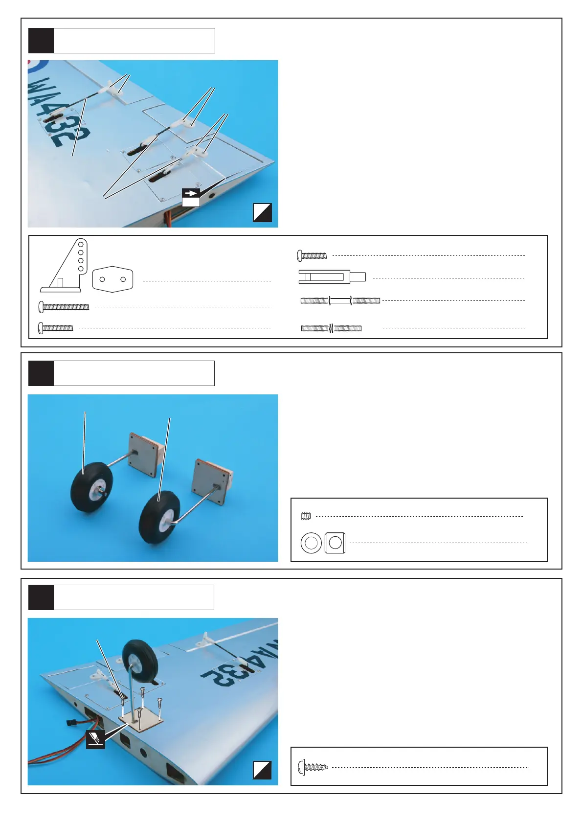
Fixed Landing Gear
2.6 x 12mm Screw
Cut away the covering and mount the fixed landing
gear on main wing with 2.6x12mm screws.
Insert 4mm wire to the wheel, then add the 4.2mm
collar and lock in place with the 3x4mm set screw.
Note: Skip to Step #7 if you are using retractable land-
ing gear.
 Loading...