MIOX AE Series Operators Manual
102-00085-E Page 5
List of Figures
Figure 1 AE System ................................................................................................................... 8
Figure 2 Strut Bolt Pattern ........................................................................................................ 12
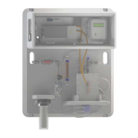
Figure 3 AE Series OSG Compartments ....................................................................................... 14
Figure 4 System Side Panel Connections ..................................................................................... 15
Figure 5 Brine Feed Connection ................................................................................................. 18
Figure 6 Float Valve Assembly and Detail .................................................................................... 20
Figure 7 Internal View Float Valve Assembly and Detail ................................................................. 21
Figure 8 Oxidant Tank Vents ..................................................................................................... 22
Figure 9 Safety Placards ........................................................................................................... 23
Figure 10 Ventilation Requirements ............................................................................................ 24
Figure 11 Level Switch Installation ............................................................................................. 24
Figure 12 Oxidant Tank Level Switch Wiring to Control Box ........................................................... 25
Figure 13 System Display - Primary View .................................................................................... 29
Figure 14 System Display - Secondary View ................................................................................ 30
Figure 15 External Controls Relay .............................................................................................. 34
Figure 16 Rupture Disk ............................................................................................................ 41
Figure 17 Ruptured Diaphragm .................................................................................................. 42
List of Tables
Table 1 Feed Water Requirements ............................................................................................. 17
Table 2 Fault Troubleshooting Guide .......................................................................................... 38
Table 3 Additional troubleshooting procedures ............................................................................. 40