2 1 2 E
9
Operating instructions and warnings
only for qualified personnel
6 OPERATING CONDITIONS
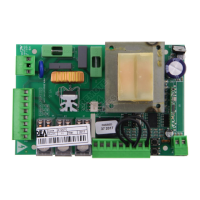
212 E control board is designed for the automation of swing gates operated by 230 V ~ motors.
This control board has been designed and tested for operation under “normal” conditions for both
residential use.
WARNING Using the product under unusual conditions not foreseen by manufacturer may cause
dangerous situations; this is the reason why all the conditions prescribed in these instructions must be
followed. A2
WARNING Under no circumstance must the product be used in an explosive environment or sur-
roundings that may prove corrosive and damage parts of the product. A3
7 ASSEMBLY AND WIRING INSTRUCTIONS
Connect to the power supply 230 V ~ 50 Hz through a multi pole switch or a different device that can
ensure multi pole disconnection from the power supply, with a contact opening of 3,5 mm. Use a cable
with a minimum section of 3 x 1,5 mm² (e.g. a H07RN-F type).
Table 1 terminal boards connection
1-2 F N 230 V ~ - 50 Hz power supply input (L=phase, N=neutral)
3-4
230 V ~ 50 Hz max 40 W flashing light output
5-6-7
2nd motor output max 500 W (5 = open, 6 = common, 7 = close)
8-9-10
1st motor output max 500 W (8 = open, 9 = common, 10 = close)
11-13 24Vsic
24 V ~ power supply output for controlled safety devices. To be used as power supply
for photocells transmitters and of safety devices when testing these latter before each
gate operation
12-13 24Vaux
24 V ~ power supply output for auxiliary circuit and uncontrolled safety devices. To
be used as power supply for any auxiliary device of photocells receivers and for safety
devices when testing these latter before each gate operation
14 FCC
WARNING 1 motor working: N.C. input end of stroke while closing. If unused, short
circuit to terminal n. 19
WARNING 2 motors working: unused input, short circuit to terminal n. 19
15 FCA/SIC2
WARNING 1 motor working: N.C. input end of stroke while opening. If unused, short
circuit to terminal n. 19
WARNING 2 motors working: N.C. input, external safety device. In the case of activa-
tion, it inverses the movement. If unused, short circuit to terminal n. 19
16 SIC1
N.C. input, external safety device. In the case of activation, it inverses the movement.
If unused, short circuit to terminal n. 19
17 FOTO
N.C. photocell input, in thecase of activation while closing, it inverses the movement.
If unused, short circuit to terminal n. 19
18 START
N.O. start input. If activated it opens or closes the gate. It can work in “reversal” mode
or “step by step” (see paragraph 8.5). It can be used also for a temporized contact
connection.
19 COM Common inputs
20
Antenna signal
21
Antenna ground
8 OPERATING INSTRUCTIONS
After making all connections to the terminal board, remember to short-circuit all unused input, and power
the card.
1
2