DIGIRAD N
12
2 PRODUCT DESCRIPTION
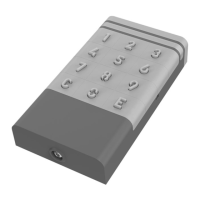
DIGIRAD N is a four-channel radio keypad selector designed to control compatible DEA SYSTEM command units and/or receivers.
The selector can work both indoors and outdoors and being powered by batteries, it does not require wiring.
The integrated circuit has 2 distinct serial numbers. The fi rst S/N_D (device serial number) is used to identify the selector within the DEA
System NET-LINK ecosystem and cannot be changed, the second S/N_R (radio serial number) is used to send commands to the paired
devices by simulating the operating logic of a 4-buttons remote.
3 TECHNICAL DATA
Power supply 2x CR2450 batteries in series (lithium-ion, 3V)
Dusk sensor
Keypad
Status LEDs
Battery life
2 years with 10 activations per day (with
backlight time-out at default)
Radio frequency 433.92 MHz
Radio coding HCS Rolling Code, Dip Switch, D.A.R.T.
Radio channels 4
Radio signal range
200m in open fi eld
40m for indoor use
Access codes Max 300
Code length 2 to 8 digits
Degree of protection IP54
Operating temperature -20÷50 °C
Product dimensions 137x74x28 mm
Product weight 200 g
4 INSTALLATION AND ASSEMBLY
WARNING: For assembly and / or disassembly operations, always use the most appropriate equipment, meticulously following the
regulations in force in the sales Country.
WARNING: Remove the lid carefully following the instructions. Do not remove parts by forcing components.
WARNING: Fixed installation controls (buttons, etc.) must be located out of the reach of children at least 150 cm above the ground.
WARNING: Do not mount the selector near or even on metal surfaces (including mirrored glass) as this could compromise its operation,
in particular with regard to the transmission distance.
Before installation, identify the place to mount the selector making sure that the distance from the respective receivers does not exceed
the maximum declared range (see paragraph “3. TECHNICAL DATA”).
It is also advisable to perform some transmission tests from a greater distance, in order to ensure correct operation even with a fl at
battery.
Please proceed according to the following points:
• Open the device by unscrewing and removing the special screw on the bottom with the wrench provided;
• Drill the support surface following the measurements indicated in Pic. 4, taking into account whether it requires the use of the
supplied expansion plugs;
• Place the insulating pad between the wall and the rear base of the selector and fi x the base with the supplied screws (Pic. 5);
• Remove the 2 insulating tabs from the batteries, checking that the selector works correctly (Pic. 3);
• Before closing the upper part, make sure that the silicone gasket has been reassembled and is not damaged;
• Hook the upper part of the selector to the base previously fi xed to the wall and tighten the special screw on the bottom (Pic. 6).
WARNING: When reassembling the upper part of the selector, slightly tilt the shell to facilitate the interlocking and apply a slight downward
pressure (Pic. 7).
 Loading...