EN-3
6 INPUTS AND OUTPUTS CONFIGURATION
Each input/output may be confi gured for the desired function if the installation
requires different and/or additional controls compared to the standard
described in the wiring diagrams.
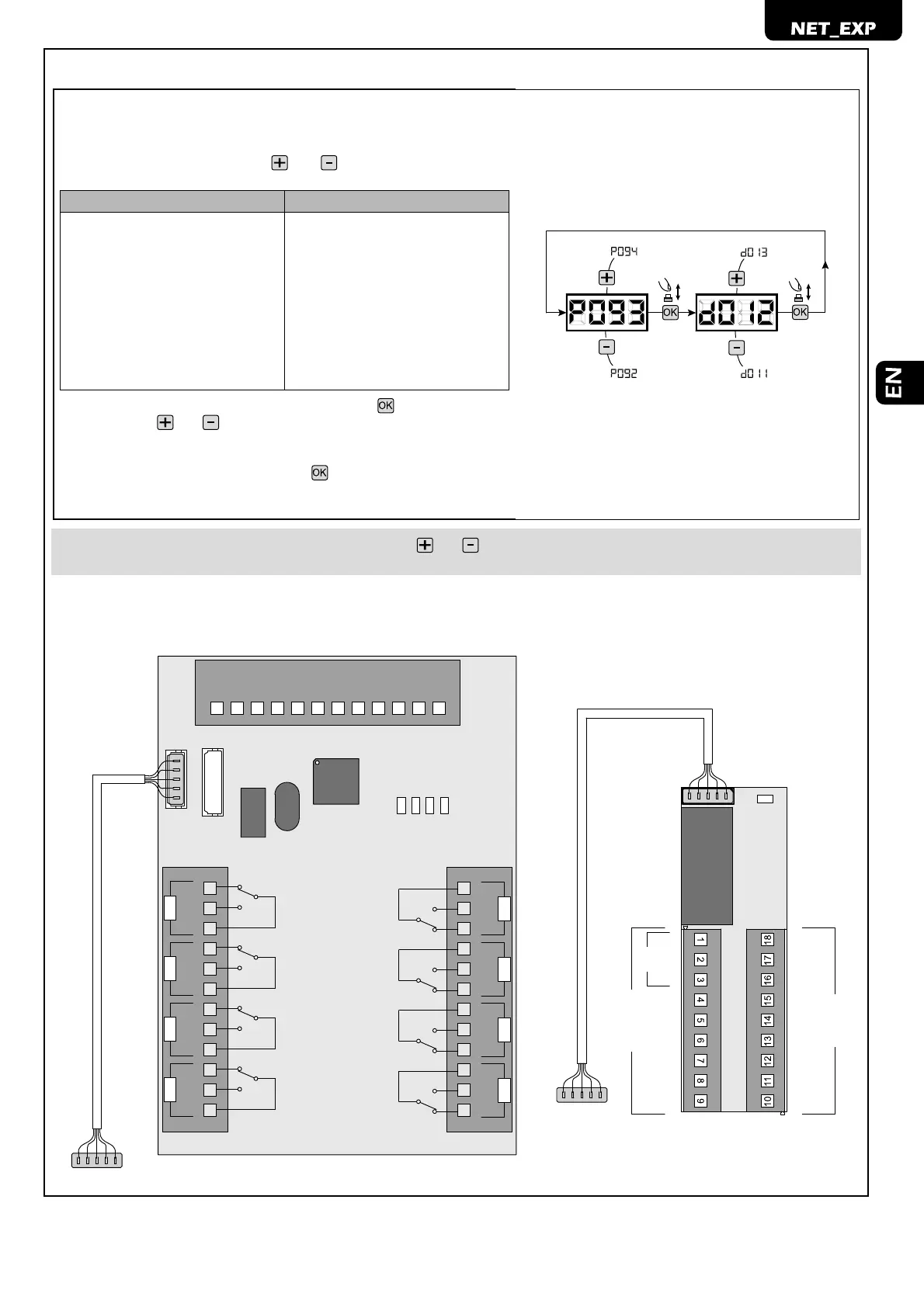
1. Scroll the parameters with the
and buttons until the parameter
desired is displayed:
INPUT OUTPUT
● P085=for INPUT 1; ● P091=for OUTPUT 1;
● P086=for INPUT 2; ● P092=for OUTPUT 2;
● P087=for INPUT 3; ● P093=for OUTPUT 3;
● P088=for INPUT 4; ● P094=for OUTPUT 4;
● P089=for INPUT 5; ● P095=for OUTPUT 5;
● P090=for INPUT 6; ● P096=for OUTPUT 6;
● P097=for OUTPUT 7;
● P098=for OUTPUT 8;
2. Access the parameters (i.e. P093) by pressing the
button;
3. By using the and , buttons, set the value corresponding to the desi-
red functions (refer to the “confi guration parameters” table on page EN-
8);
4. Confi rm the selection by pressing the button (P093 appears on the
display screen).
5. Carry out the connection you have just confi gured.
WARNING At the end of the confi guration procedure, use the and buttons until the “- - - -“ symbol appears; the automatism is now
pending commands for normal functioning.
NET_EXP NET_EXP mini
C
C
IN5
IN4
C
C
IN6
IN3
C
IN2
IN1
C
C
N
C
C
N
C
C
N
C
NO
NO
NO
C
N
C
NO
NC
C
N
C
C
N
C
C
N
O
NO
NO
NC
C
N
O
OUT5
OUT6 OUT7 OUT8
OUT1
OUT2 OUT3 OUT4
--> TO NET BOARD -->
LED 4
LED 3
LED 2
LED 1
--> TO NET BOARD -->
NC
NO
C
IN1
IN1
IN2
IN3
IN4
IN5
IN6
C
C
CC
C
IN4
IN2
IN3
NET BOARD
OUT1
NET-EXP
MINI
LED
 Loading...