379
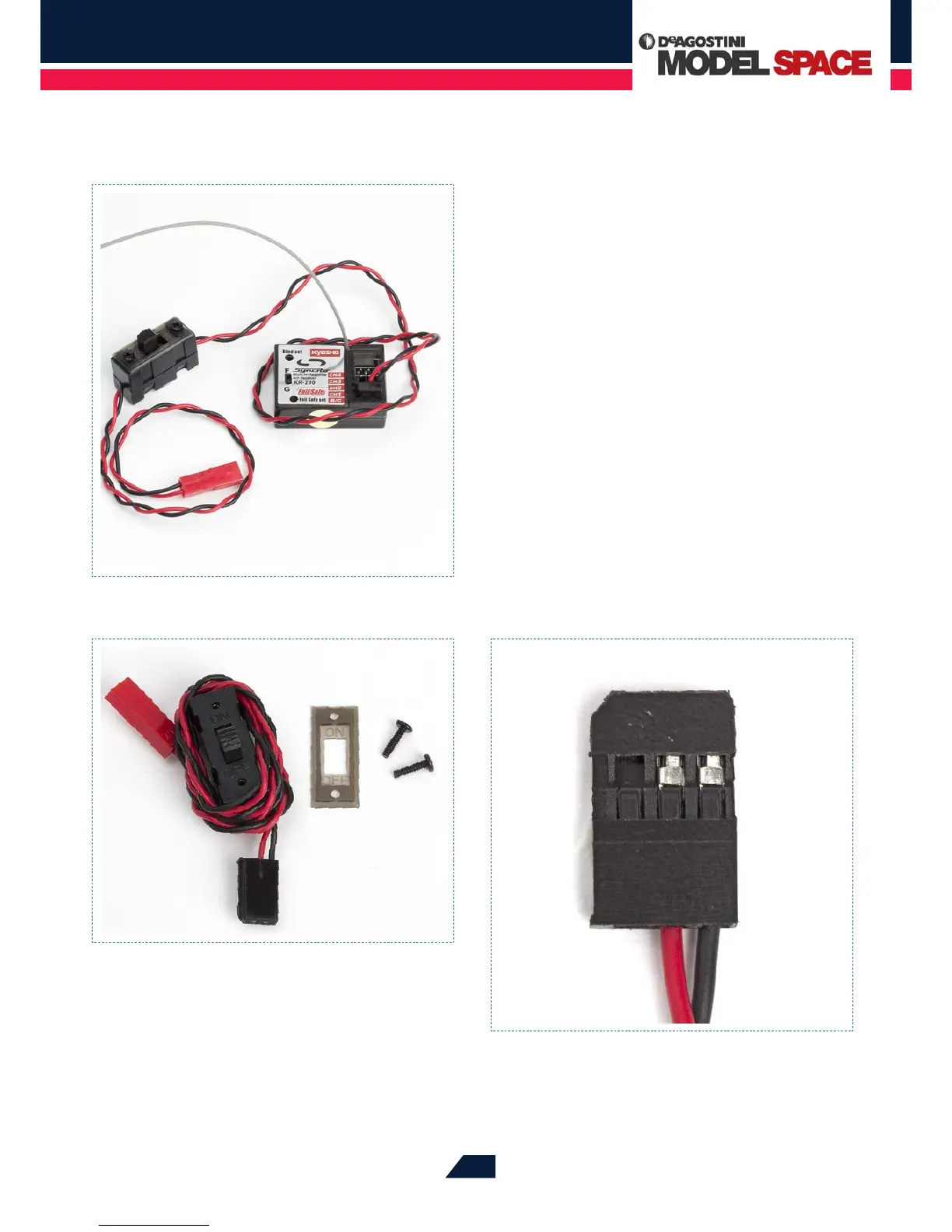
The switch itself is a slide switch. Connected to it are a
pair of two-core cables (one core with red insulation, the
other black). These cables are soldered to the switch, which
is housed in a rectangular plastic casing. The on and o
switching process is carried out by a slider on the top of the
switch, which remains in whichever position is selected.
The ON and OFF markings are on a cover plate surrounding
the slider. You have to remove this plate when you mount
the switch on the right chassis plate of your model, so
always make sure that the plate is the right way round
when you replace it.
The plugs of the two cables attached to the switch are
dierent colours, and the cable with the red plug will be
connected to the battery box and the one with the black
plug to the receiver. When the slider is nearer to the cable
with the red plug, the switch is sitting in its OFF position
and the RC receiver and the two servos are disconnected
from the batteries.
When mounting the switch on the right chassis plate, you rst need to
remove its cover plate by removing the two retaining screws. This plate also
carries a visual indication of whether the switch is in the ON or OFF position,
so make sure that it is the right way round when you replace it.
The cable with the black plug connects the switch to the receiver.
The red and black wires are securely clamped to the metal contacts
in the plastic body of the plug.
The switch is connected upstream of the receiver, from which the servos
receive their power.