MAN-PTS-GB, Revision 9, BSC, 15-FEB-2017 15/46
3 CONSTRUCTION AND OPERATION
The chamber is the main part of the PTS technology. The PTS filter is located in the upper part of
the chamber, between the body and the cover. The system consists of 4 valves which are
connected to a control system. The valve "product inlet" V1 and the valve "product outlet" V2
are directly mounted on the chamber. The valve connected to the vacuum and the valve
connected to a pressure source are either connected to the PTS cover by a flexible hose or
directly mounted on the PTS cover.
The valves open and close automatically according to a logical sequence in order to alternate
the filling and emptying cycles of the PTS chamber. The system, from its principle, can transfer
products dust-free without changing their homogeneity. It can, furthermore, fill closed vessels
without the introduction of oxygen.
The suction and emptying times and the frequency of the cycles can be easily adjusted
according to the process conditions. The figures below describe the different PTS steps in detail.
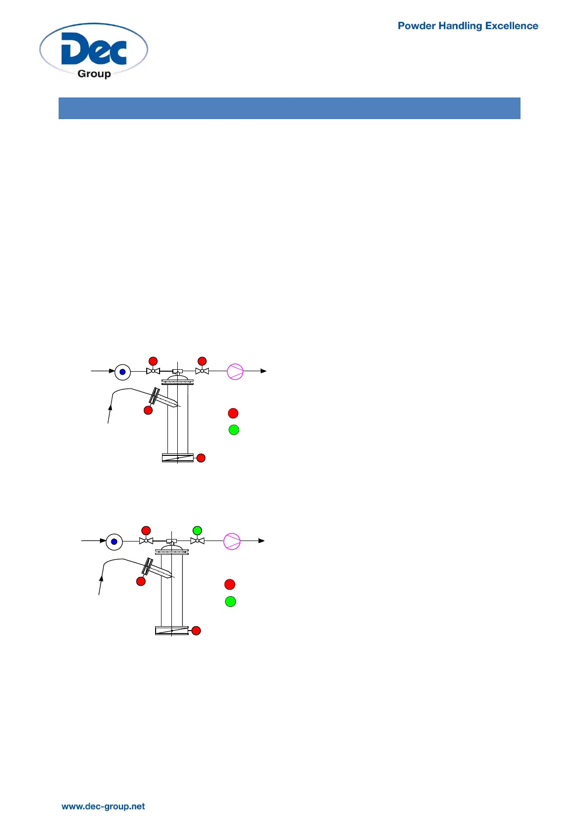
In the shutdown position, all the valves
are closed.
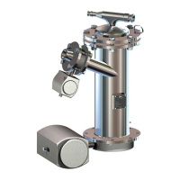
At the beginning of the suction phase,
the vacuum valve V3 opens. Vacuum is
created in the PTS chamber by the
vacuum pump connected to valve V3.
VACUUM
PUMP
PRESSURE
POWDER
V1
Valve closed
Valve open
V2
V3
V4
VACUUM
PUMP
PRESSURE
POWDER
V1
Valve closed
Valve open
V2
V3
V4