EC-20, EC-10 and EC-5 User’s Manual
2. About the EC-20, EC-10, EC-5
6
ECH
2
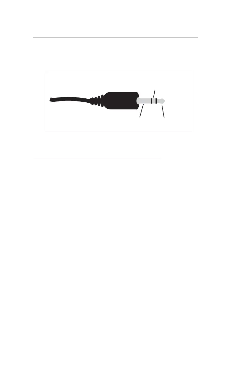
O Check. Below is a diagram showing the wiring
configuration for this connector.
Fig. 2: 3.5mm “Stereo Plug” wiring configuration
Wiring to Non-Decagon Dataloggers
Models with stripped and tinned leads are pre-config-
ured for connecting to non-Decagon dataloggers. Sim-
ply wire the lead into the datalogger as described in
“Connecting to a Datalogger” in Chapter 4.
If your model uses the standard 3.5mm plug, you have
two choices when attaching the sensor to non-Decagon
dataloggers. First, you can clip off the plug on the sen-
sor cable, strip and tin the wires, and wire it directly into
the datalogger. This has the advantage of creating a
direct connection with no chance of the sensor becom-
ing un-plugged; however, it then cannot be used in the
future with a Decagon Em50 or Em5 logger. The other
choice is to obtain an adapter cable from Decagon. The
3-wire sensor adapter cable has a connector for the sen-
sor jack on one end, and three wires on the other end for
connection to a datalogger (this type of wire is often
referred to as a “pigtail” adapter). Both the sensor wire
and adapter cable wire have the same wire output
Analog
out
Ground
Excitation
 Loading...