2
Serial Telemetry (Connecting External Devices – Page 6)
Digital Sprite 2 supports a number of dome manufacturers using serial (twisted pair RS-485)
telemetry. Serial telemetry requires a twisted pair connect from the dome to the Bus A
connection on the Digital Sprite 2.
Note: The D-type connectors on the Digital Sprite 2 are no longer used for telemetry.
Serial telemetry connection
The serial telemetry port on the Digital Sprite 2 is a screw terminal labelled ‘Bus A’. The
connection is as follows:
Bus A RS-485
+ Data A (TX+)
- Data B (TX-)
Bus B is also used if Sensormatic RS-422 telemetry is used. The connection is as follows:
Bus A RS-422 Bus B RS-422
+ TX+ + RX+
- TX- - RX-
Note: The serial telemetry connection must be configured for the correct type of dome in the
‘System Options’ menu.
External CD Writer (Page 7)
Although the DS2 CD has an internal CDR, it is also compatible with the following external SCSI
CD writers:
Yamaha CRW2200 SX
Yamaha CRW3200 SX
Yamaha CRW-F1 SX
Plextor Plexwriter PX-W1210TSE
Plextor Plexwriter PX-W4012TSE (This is the only currently available CDR)
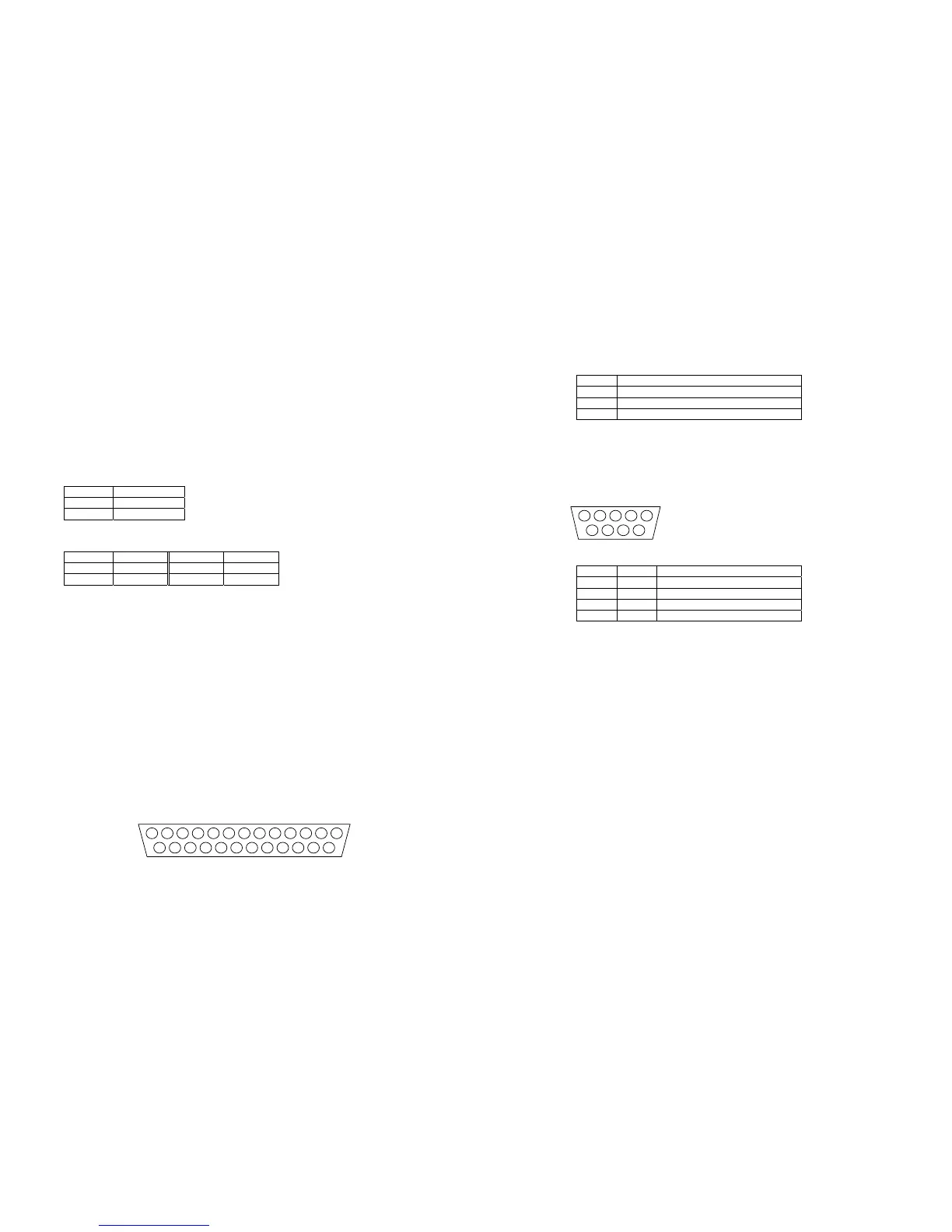
Connecting alarms (page 10)
There are now auxiliary alarm contacts on the rear of the unit labelled ALARMS IN. These can
be used instead of, or in conjunction with external alarm modules (DM/CI01).
The pin-out for the ALARMS IN connector are as follows (view from solder side).
PIN ALARM NUMBER
1 – 16 1 – 16
17 Global alarm input (default) or Schedule
21 – 25 Ground
Connecting to the Relays (page 10)
There are extra relays available at the rear of the unit labelled RELAYS.
The pin-out for the RELAYS connector is as follows (view from solder side).
Relay PIN RELAY FUNCTION
R3 1 & 6 Camera Fail
R4 2 & 7 Hard Disk Fail
R5 3 & 8 Network Relay
R6 4 & 9 Not currently used
The corresponding relay will close when there is a Camera fail, Hard disk fail, or the Relay
button is pressed whilst using DM Network Viewing Software.
Relays R1 and R2 are on the green connector at the rear of the unit.
WARNING: The maximum rating of all the relays is 500mA @ 48V. Exceeding this load will
damage the relays.
Schedule (Page 16)
The Set/Unset option in the Night and Weekend schedule can now use the AUX ALARM inputs on
the rear of the unit to trigger the schedule to start and stop.
Camera Recording (Page 16)
This menu has been removed (now replaced with the Advanced Record Schedule page).
Record Schedule (Page 17)
The maximum record rate (Standard PPS or Event PPS) is now up to 50PPS for PAL standard
cameras, and 60PPS for NTSC standard cameras.
Note: A record rate of 50/60PPS is only achievable with 2 cameras, a single camera can record
at a maximum of 25/30PPS.