Warning
Only suitable for potential-free contacts.
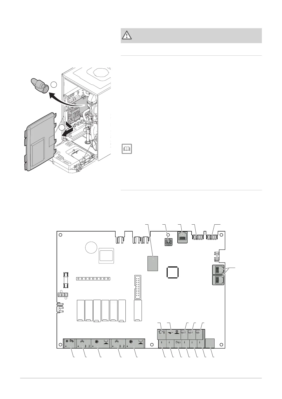
6.6.6
Access to the PCB housing
1. Unscrew the two screws located under the front panel by a quarter
turn.
2. Remove the front panel.
3. Tilt the instrument box forwards by opening the clips on the sides.
4. Remove the air intake silencer.
5. Unclip the 4 clips on the left side of the PCB housing cover.
6. Swing the cover to the right and pull it forward to remove the cover
from the boiler.
7. Connect the cables to the appropriate terminals on PCB SCB-10.
8. Position the upper hinges of the cover in the right position of the PCB
housing.
9. Press all hinges of the cover into place.
10. Close the 4 clips on the left side of the cover.
11. Fit the air intake silencer.
12. Reassemble the front panel in the reverse order.
For more information, see
Opening boiler, page 104
6.6.7 Description of the SCB-10 PCB
Different heating zones can be connected to the SCB-10 PCB. Two zones
are designated for heating and one for domestic hot water.
The connections for the sensors or pumps of each zone are on the PCB.
Fig.41 SCB-10 PCB
X2 X3
+TA-
TA
Tsyst Tsyst Tdhw Tflow Tflow Tflow
C AB21
R-Bus
Tout
R-Bus
R-Bus
12
3
4
+ -
Status
C AB
0-10V
N L
B
N
N L TS
N L
TS
A
N
23
2218 2019 21
5
14131211 15 16 17
43
21
109876
1 Outdoor temperature sensor
2 Programmable and 0-10 V input
3 Room temperature sensor - circuit C
4 Room temperature sensor - circuit B
Fig.40 Access to the PCB
6 Installation
7686707 - v.01 - 06092018 AMC 41
 Loading...