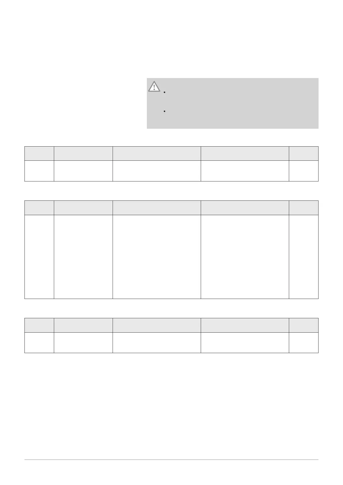
A
Boiler (master)
B
Boiler (slave)
C
Low loss header
D
Direct zone - CircA1 (Boiler A)
E
Mixing zone - CircB1 (Boiler B)
F
DHW zone - CircA1 (Boiler A)
A-B
S-BUS cable kit
Boiler A: resistor on SCB-10 connector X5, Cable
on SCB-10 connector X4
Boiler B: resistor on SCB-10 connector X5, Cable
on SCB-10 connector X4
Caution
If the tank is fitted with a Titan Active System® corrosion
protection anode, connect the anode to the inlet (+ TA on the
anode, - on the tank).
If the tank is not fitted with a corrosion protection anode, put the
simulation connector in place (delivered with the DHW sensor
(accessory))
Tab.40 Boiler A: Installation Setup > SCB-10 > Cascade management B > Parameters, counters, signals > Parameters
Code Display text Description Range Adjust
ment
AP083 Enable master func Enable the master functionality of
this device on the S-Bus for system
control
0 = No
1 = Yes
1
Tab.41 Boiler A: Installation Setup > SCB-10 > DHW 1 ( DHW layered tank ) > Parameters, counters, signals > Parameters
Code Display text Description Range Adjust
ment
CP022 Zone Function Functionality of the zone 0 = Disable
1 = Direct
2 = Mixing Circuit
3 = Swimming pool
4 = High Temperature
5 = Fan Convector
6 = DHW tank
7 = Electrical DHW
8 = Time Program
9 = ProcessHeat
10 = DHW Layered
11 = DHW Internal tank
31 = DHW FWS EXT
10
Tab.42 Boiler B: Installation Setup > CU-GH08 > Gas fired appliance > Parameters, counters, signals > Parameters
Code Display text Description Range Adjust
ment
AP102 Boiler Pump function Configuration of the boiler pump as
zone pump or system pump (feed
lowloss header)
0 = No
1 = Yes
0
6 Installation
64 AMC 7686707 - v.01 - 06092018
 Loading...