INSTALLATION INSTRUCTIONS
(PLEASE READ CAREFULLY AND THOROUGHLY BEFORE INSTALLING)
INSTALLATION SHOULD ONLY BE PERFORMED BY AN AUTHORIZED PROFESSIONAL
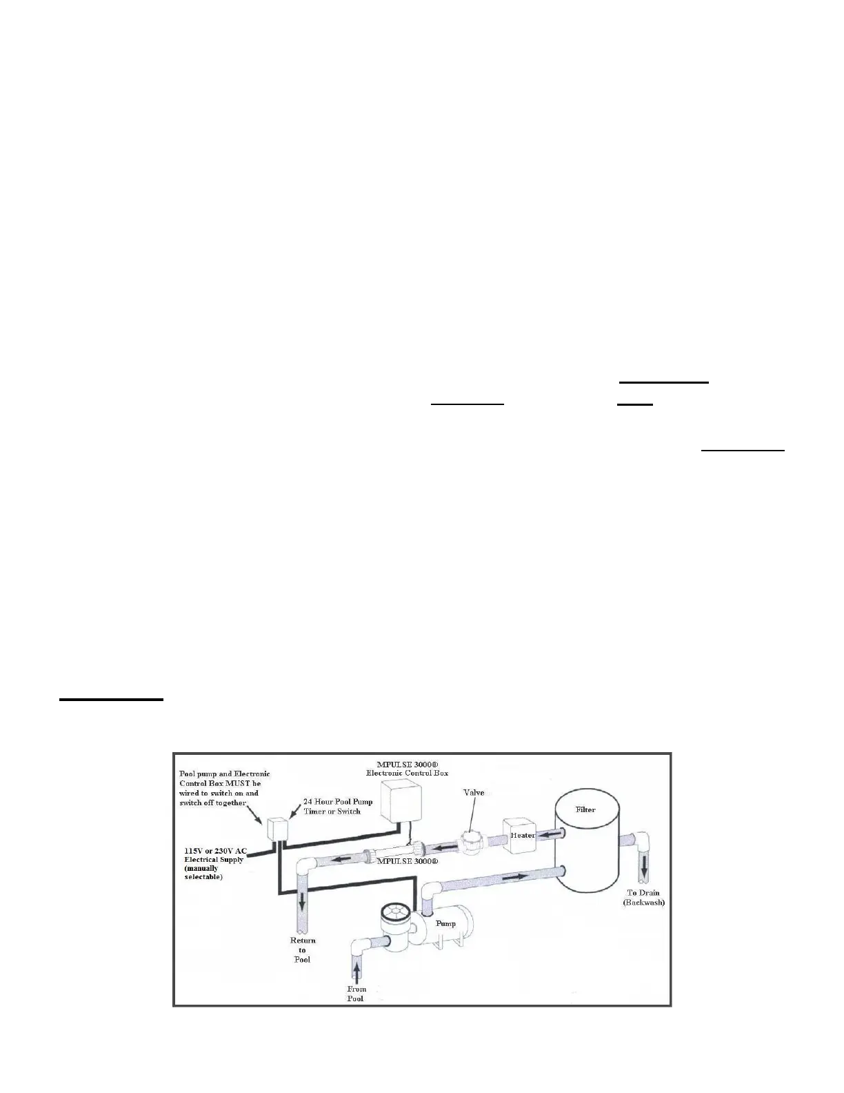
1. The Chamber must be installed in line on the return side (after the filter) to the pool:
a. Primary position: after the heater, before any salt/chlorination system.
b. Secondary position: after the filter, before the heater.
This unit may be installed vertically or horizontally and has no required flow direction.
Each of the unions on the chamber contains an o-ring. Ensure that these o-rings are
lubed and in the proper position prior to tightening the unions.
2. The Electronic Control Box must be installed no further than 6 (six) feet from the
chamber. It must be connected to the load side of the timer only to run with the
circulation pump.
a. The length of the cable from the chamber to the Electronic Control Box CANNOT
be lengthened or shortened – it is a specific length to ensure that the impedance of
the chamber is matched properly with the control head to maximize calcium
scaling prevention.
b. The AC power connection from the electronic control head to the timer is the
responsibility of the installer and must meet applicable UL standards and must be
installed in accordance with all local ordinances, and the National Electric Code
(NEC) NFPA 70.
3. Connect the plug on the low-voltage cable from the chamber to the appropriate male
ended plug at the bottom of the Electronic Control Box (see following page for further
instruction).
CAUTION: The low-voltage cord is a set length for proper operation, if the
length is modified, the warranty will be void. Use only approved wiring for
power connection.