4
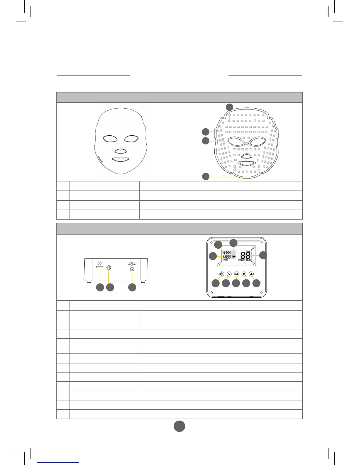
Control Panel Components
A Mask connecting USB port Port to connect the control panel to the mask via the USB cable
B Power indicator Bulb illuminates blue when power is connected
C Power cable port Port to connect the control panel to the electricity supply
D Power button To turn the mask ON and OFF or to PAUSE treatment
E Dual - Wave treatment
button
To select the required Dual - Wave programme or when used in
combination with an option from Button F for a Tri - Wave programme
F Mode button To select the required Single wavelength (colour) for treatment
G Decrease minutes button Reduce the required treatment duration
H Increase minutes button Increase the required treatment duration
I Dual - Wave indicator Indicates the dual - wave programme selected by Button E
J Mode indicator Indicates the single wavelength (colour) selected by Button F
K Action display Ticks around indicating the programme cycle is running
L Running time Indicates time selected or time remaining on the programme
Mask Components
1 Surface mounted LED’s To emit the required wavelength of light
2 Strap connecting holes To secure the retaining strap to the mask if required
3 Soft rubber eye protector For safety and comfort during treatment
4 Power supply port Port to connect the mask to the control panel via the USB cable
1
2
3
4
COMPONENTS
EXPLAINED
Front
Reverse
B CA
D E F G H
Top
Front
K
L
J
I