NI-029 Rev. 7 ⇒ September 2016
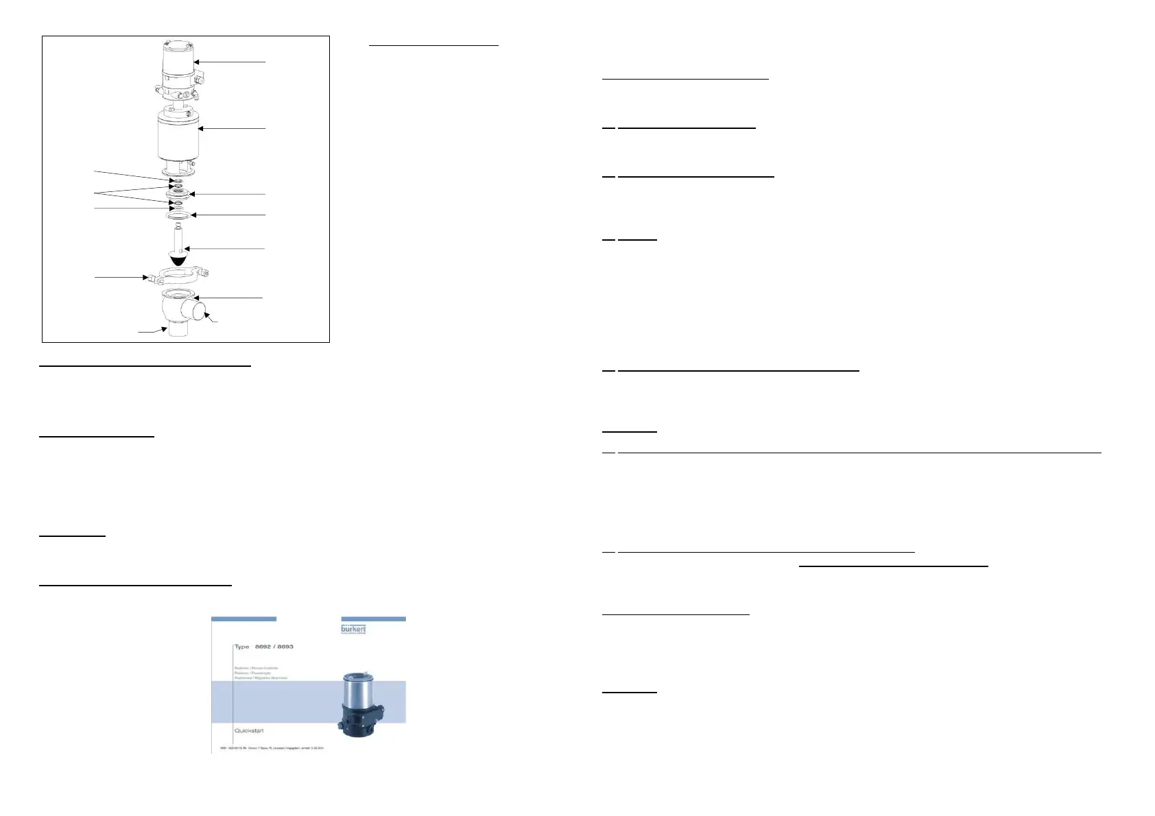
DCX3 CONTROL VALVE
1 – DCX3 valve body
2 – Piston
3 – Seal
4 – Seal support plate
5 – Actuator cylinder
6 – Positioner Burkert 8693
7 – Collar clamp
8 – Seal
9 – Ring (Qty 2)
10 – Seal
1
.
D
ESCRIPTION OF THE CONTROL VALVE
:
DEFINOX control valves with position memory are ideal for the control and regulation of flow rates,
temperatures, levels, pressure and for use in biotechnology. DEFINOX control valves are currently
available in sizes DN 25 to DN 104 in standard food grade and aseptic versions. These valves have a
simple loop function.
2 . The PID controller (Proportional - Integral - Derived)
The controller processes the control discrepancy. This calculator compares the set point value with the
actual value and supplies an output signal depending on this difference (processes the 4-20 mA output).
Two types of control are possible:
- Manual control according to system evaluation (valve and service conditions)
- In auto-adaptive mode, the P.I.D. controller calculator automatically performs some of the
control functions
3 . The valve
The valve can operate in NO or NC with an optional metal/metal seal. The profiled disc facilitates
linearization of valve operation.
Putting DEFINOX valve into service
Refer to the attached notice Bürkert:
Follow the fitting and operating instructions carefully. Take account of the actual working conditions
and observe the technical specifications for the valve.
1
-
VALVE
IDENTIFICATION
DEFINOX control valves have an identification number. You will need this number in order to identify
the spare parts you may request.
2
- SERVICE CONDITIONS
The working conditions of this valve (pressure, temperature, fluid transported, etc.) must comply with
the general technical specifications described in the DEFINOX catalogue available on request.
3
- AIR SUPPLY CONDITIONS
The actuator is supplied with dry, filtered air at a pressure of 4.5 to 8 bar. The actuator air couplings are
designed for a 4/6 diameter hose fitting. The valve has a max. working pressure of 6 bar, a max.
temperature of 140°C and an acceptable vacuum of 0.4 bar.
4
- SEALS
Unless otherwise specified in the order, DCX3 control valves are equipped with the
following seals :
• EPDM or FKM for the O-rings
Choosing the right type of seal is critical to correct valve operation. This is not always easy,
as all characteristics of the fluids circulating through the valve must be taken into
consideration. We can help you make this choice. Ensure that the grease used is compatible
with the elastomer seals, particularly EPDM.
5
- N.C. –, N.O. – AND D.A. CONFIGURATION
DCX3 control valves are supplied as standard in an N.C. configuration and require an air
supply to remove the piston.
The valves can be supplied in an N.O. or D.A. configuration on request.
Important : Before changing the configuration, consult the maintenance instructions (IT.DFX.036).
6
- PRECAUTIONS TO BE TAKEN WHEN CARRYING OUT WELDING OF THE BODIES
Adjust the pipes : check the straightness, the out-of-roundness and the offset (play<0.5 mm),
to limit the restrictions created by welding.
Any modification to the valve body for the purpose of welding must be carried out with the
agreement of Definox.
Support the pipes at least 10D from the valve (valve nominal diameter).
7
- INSTALLING THE VALVE ON THE PROCESS LINE
To install the valve on the process line, the weld-on body must be separated from the rest of the valve
to prevent seal damage.
To carry out this simple operation, proceed as follows while referring to the diagrams :
A- DCX3 (single-body valve)
Put the valve in the open position. With an N.C. configuration, the actuator ( 5 ) must be supplied with
air.
Remove the clamp ( 7 ) . Shut off the air and separate the body ( 1 ) from the rest of the valve. Weld the
body to the pipes.
Important : For subsequent actuator and piston disassembly, you will need to be able to remove one of
the bodies (preferably the top one) from the line. Make sure this body is welded to a removable section
or between fittings.
5
4
2
8
8
7
9
10
6
 Loading...