Do you have a question about the Definox Sorio Basic 3EV and is the answer not in the manual?
General advice for intervention, configuration changes, and maintenance manual reference.
Specifications for dry, filtered air at 10µm and operating pressure of 5 to 7 bars.
Details on cable gland type, terminal block voltage, conductor size, and cable diameter.
Minimum clearance of 50 mm required above the cover for disassembly and handling.
Turn the cover counterclockwise to the stop, then pull up to remove.
Screw and tighten the cam using the appropriate tool and torque values.
Align the indexing pin to the 1/8 Gas hole for correct base positioning.
Screw in and tighten the non-detachable CHC screws to fix the base.
Pass cable through gland, connect to terminal block, and tighten nut securely.
Position cover, press onto base, and lock by turning clockwise until aligned.
Connect actuator channels to unit channels and apply pressure to the P channel.
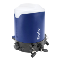
The DEFINOX Sorio® Basic 3EV control unit is a device designed for controlling pneumatic actuators, specifically 3-way valves, in industrial applications. It integrates pneumatic and electrical components to manage valve positions and provide feedback.
The Sorio® Basic 3EV control unit serves as the interface between a control system and a pneumatic actuator. It receives electrical signals to operate solenoid valves (EV1, EV2, EV3), which in turn direct compressed air to the different chambers of the actuator, thereby controlling the valve's open, closed, or intermediate positions. The unit also incorporates sensors (High Position and Low Position) to provide feedback on the valve's current state, allowing for precise monitoring and control. The "3EV" in its name indicates its capability to control 3-way valves, likely through a combination of three solenoid valves.
Air Quality:
Electrical Specifications:
Pneumatic Connections: The unit features specific ports for pneumatic connections:
Mounting the Cam: The cam is a critical mechanical component that interacts with the position sensors. It must be securely mounted and tightened according to specific torque values, which vary depending on the cam type (M5, M6, M8, M10, M12, M16) and whether it's male or female. Tools like Allen spanners (2.5) or open-end spanners (17) are used for this. The tightening torque ranges from ≥ 2 N.m to 20 Kgf.cm.
Assembling the Actuator Base: The actuator base is positioned by aligning an indexing pin with a 1/8 Gas hole, ensuring correct orientation. It is then fixed to the actuator using two non-detachable CHC screws, tightened to a torque of ≥ 1 N.m or 10 Kgf.cm.
Assembly of Cable / Cable Gland: Electrical connections involve unscrewing a nut from the cable gland, passing the connection cable through it, connecting the cable to the terminal block, and then tightening the nut. This process ensures a secure and sealed electrical connection.
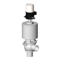
Pneumatic Connection on VEOX: The pneumatic connections are crucial for directing air to the actuator. This involves:
Locking and Unlocking the Cover: The cover is designed for easy access while maintaining protection.
General Maintenance: For any intervention or configuration change, users are directed to consult the maintenance manual (NM-278), available on the DEFINOX website (http://www.definox.com/). This emphasizes the importance of following official guidelines for servicing the unit.
Clearance for Disassembly: A minimum clearance of 50 mm above the cover is required for disassembly and handling of the unit. This ensures sufficient space to remove the cover and access internal components without obstruction.
Cover Design: The cover's design, with its simple twist-and-pull mechanism, facilitates quick access to the internal components for inspection, wiring, or component replacement, streamlining maintenance tasks.
Modular Design: The unit appears to have a modular design, with separate components like the cam, actuator base, and terminal block, which could simplify replacement of individual parts if needed.
The DEFINOX Sorio® Basic 3EV control unit is a robust and precisely engineered device for automated valve control, designed with both operational efficiency and ease of maintenance in mind.
| Brand | Definox |
|---|---|
| Model | Sorio Basic 3EV |
| Category | Control Unit |
| Language | English |