EasyManua.ls Logo

Definox Sorio Basic 1EV - User Manual

Definox Sorio Basic 1EV
2 pages
Print Icon
To Next Page IconTo Next Page
Loading...
NI-267 index 1 June 2021
Cam
INSTALLATION GUIDE
Sorio® Basic 1EV control unit
www.definox.com
DEFINOX SAS
3 Rue des Papetiers - Z.A.C. de Tabari 2
44190 Clisson - France
:
+33 (0)2 28 03 98 50
:
+33 (0)2 28 03 88 00
E-Mail: info@definox.com
Recommendations
IMPORTANT
For any intervention or configuration change, see the
maintenance manual (NM-278) available on the website:
http://www.definox.com/
AIR QUALITY
Dry and filtered air at 10µm (DIN ISO 8573-1)
Operating pressure: 5 to 7 bars
ELECTRIC
M16 x 1.5 cable gland
Digital terminal block version:
Operating voltage:
Digital : 24 VDC only _ +/- 5%.
Conductor section: 0.5mm² recommended and 0.75mm²
max.
Ø cable : 4 to 10 mm.
IMPORTANT
For disassembly and handling of the unit, provide a minimum
clearance of 50 mm above the cover.
Locking and unlocking the cover
Cover locked
Cover unlocked
Turn the cover counterclockwise to bring the fin to the
stop, then remove the cover by pulling it up.
Mounting the cam
Screw the cam and tighten with a tool according to the table (tightening torque: 2N.m or 20Kgf.cm).
Reference
Cam
Visual
Tools
7162010
M6
A
2 Nm
7162011
M8
A
2 Nm
7162012
M10
B
Open
-
end spanner 17
7162013
M12
B
Open
-
end spanner 17
7162014
M16
B
Open
-
end spanner 17
7162138
M6 Female
C
2 Nm
7162189
M5 Female
C
2 Nm
Assembling the actuator base
Position the base by aligning the indexing pin to the 1/8
Gas hole.
Screw in the two non-detachable CHC screws [A] to fix
the base on the actuator and tighten them (tightening
torque: 1N.m or 10Kgf.cm).
A
C
B
Indexing pin
A
1/8 Gas Hole
Question and Answer IconNeed help?

Do you have a question about the Definox Sorio Basic 1EV and is the answer not in the manual?

Overview

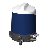
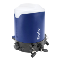
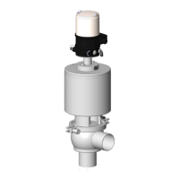
The device described in the manual is the DEFINOX Sorio® Basic 1EV control unit, an electronic control unit designed for industrial valve automation. It integrates sensing, pneumatic control, and electrical connectivity to manage valve positions.

Function Description

The Sorio® Basic 1EV control unit serves as an intelligent interface for pneumatic actuators, enabling precise control and monitoring of valve states (open/closed). It features integrated sensors for detecting high and low valve positions, a solenoid valve for pneumatic actuation, and a terminal block for electrical connections. The unit can be configured for both Normally Closed (N.C.) and Normally Open (N.O.) actuator operations, allowing flexibility in various process control applications. Its primary function is to receive electrical signals, translate them into pneumatic commands to operate an actuator, and provide feedback on the valve's position.

Important Technical Specifications

Air Quality:

  • Dry and filtered air: Must meet DIN ISO 8573-1 standards, filtered to 10µm. This ensures the longevity and reliable operation of the pneumatic components by preventing contamination and moisture-related issues.
  • Operating pressure: 5 to 7 bars. This pressure range is critical for the effective and safe operation of the pneumatic actuator connected to the control unit.

Electrical Specifications:

  • Cable gland: M16 x 1.5. This standard size ensures compatibility with common industrial cabling.
  • Digital terminal block version:
    • Operating voltage (Digital): 24 VDC only, with a tolerance of +/- 5%. This specifies the required power supply for the electronic components.
    • Conductor section: 0.5mm² recommended, with a maximum of 0.75mm². This guideline ensures proper current carrying capacity and prevents overheating or voltage drops.
    • Ø cable: 4 to 10 mm. This range indicates the compatible cable diameters for the cable gland, ensuring a secure and sealed connection.

General:

  • Minimum clearance: A minimum clearance of 50 mm above the cover is required for disassembly and handling, highlighting the need for adequate space in installation.

Usage Features

Installation and Assembly:

  • Cam Mounting: The manual details the process of mounting the cam, which is crucial for the mechanical linkage to the valve stem. Different cam types (M5, M6, M8, M10, M12, M16) are available, each with specific tightening torques (≥ 2 N.m or 20 Kgf.cm) and corresponding tools (Allen spanner 2.5, Open-end spanner 17). This modularity allows adaptation to various valve types.
  • Actuator Base Assembly: The base is positioned by aligning an indexing pin to a 1/8 Gas hole, ensuring correct orientation. It is secured with two non-detachable CHC screws, tightened to ≥ 1 N.m or 10 Kgf.cm.
  • Cable Gland Assembly: The process involves unscrewing the nut, passing the cable through, connecting it to the terminal block, and then tightening the nut. This ensures a sealed and robust electrical connection.
  • Cover Locking and Unlocking: The cover is designed for easy removal and reattachment. To unlock, it's turned counterclockwise until a fin reaches a stop, then pulled up. To lock, it's positioned in a notch, pressed down, and turned clockwise until the fins align. This user-friendly design facilitates maintenance and access to internal components.

Pneumatic Connection:

  • N.C. (Normally Closed) Actuator: For N.C. operation, pressure is applied to channel [P], and the actuator is connected to channel [1] of the box.
  • N.O. (Normally Open) Actuator: For N.O. operation, pressure is applied to channel [P], the actuator is connected to channel [ACT] of the box, and a pierced plug is used on the actuator. This clear distinction in connection methods allows for precise configuration based on the desired valve behavior.
  • Components: The unit includes a Solenoid valve (EV), Actuator air inlet (1), Exhaust (E), and connections for Air pressure (P) and Actuator Normally Closed (ACT) / Actuator Normally Open (ACT). These components work in conjunction to manage the pneumatic flow to the actuator.

Sensing:

  • The unit incorporates sensors for "High Position" and "Low Position," providing feedback on the valve's current state. This is essential for process monitoring and control system integration.

Maintenance Features

  • Maintenance Manual (NM-278): For any intervention or configuration change, users are directed to consult the maintenance manual (NM-278), available on the DEFINOX website. This centralized resource ensures that all necessary information for servicing and adjusting the unit is readily accessible.
  • Easy Cover Access: The design of the cover, with its simple lock/unlock mechanism, allows for quick and tool-free access to the internal components, facilitating inspections, adjustments, and troubleshooting.
  • Modular Design: The separate assembly steps for the cam, base, cable gland, and pneumatic connections suggest a modular design, which can simplify replacement of individual components if necessary.
  • Clear Labeling: The internal components, such as the terminal block and pneumatic connections, are clearly labeled (EV, 1, E, P, ACT), aiding in correct wiring and tubing during installation and maintenance.

Definox Sorio Basic 1EV Specifications

General IconGeneral
BrandDefinox
ModelSorio Basic 1EV
CategoryControl Unit
LanguageEnglish

Related product manuals