PAGE 3 OF 8
x Open the glass deflector panel by gently
pulling forward on the lower edge.
x Remove the aluminium filters to expose
the in
terior of the cooker hood.
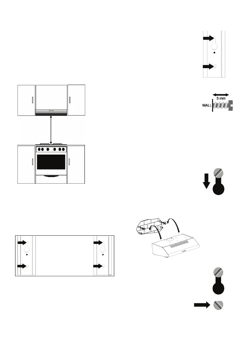
x A Keyhole slot and a retainer hole will be
visible on either side of the back panel.
x Assistance may be required to perform the
follo
wing installation tasks.
x Hold the hood in position against the wall
so th
at it aligns with the previously drawn
pencil lines.
Wall mounting.
x Mark out the location of the
key
h
o
le slots and retainer
holes on the wall.
x Use a masonry bit to drill a
hole in the wall at the top
of each marked slot and
retainer hole.
x Insert a rawl plug into each
hole.
x P
artly insert two pan head
screws, with a head
diameter slightly smaller
than the lower opening in
the keyhole slot, into the
two upper rawl plugs.
x Leave about 5mm of the
screw
sticking out.
x Lift t
he cooker hood and
slide the keyhole slots over
the two pan head screws.
x Pull down and hang the
cooker hood on the two
screws.
x Tighten the screws.
x To prevent accidental
lifting of the cooker hood,
fit a suitable screw into the
two retainer hole rawl
plugs.
x The hood should be mounted onto a flat
perpendicular kitchen wall.
x The hood must be mounted directly over
the cooking area. The minimum distance
between the cooking surface and the
underside of the hood must be 650 mm for
electric cookers and 750 mm for gas
burners.
KEYHOLE SLOTS
RETAINER HOLES
650 / 750 mm