Do you have a question about the Del Medical CM Series and is the answer not in the manual?
| Category | Medical Equipment |
|---|---|
| Series | CM Series |
| Manufacturer | Del Medical |
| Type | X-Ray System |
| Detector Type | Digital Radiography (DR) Flat Panel Detector |
| Battery Operation | No |
Summarizes features, regulatory, and compatibility requirements for the generator.
Describes the CMP 200 X-ray generator and its main components.
Lists the main features and available options for the generator.
Details the technical specifications for radiographic performance.
Details operating and storage environmental parameters for the generator.
Provides guidance and manufacturer’s declaration on electromagnetic emissions.
Details electromagnetic immunity requirements and guidance for the generator.
Covers conducted and radiated RF immunity tests and guidance.
Explains EMC compliance requirements for the generator.
Lists hazardous substances in compliance with RoHS regulations.
Covers crucial safety information, warnings, and symbols related to X-ray equipment.
Describes advisory symbols used for safety warnings on the unit and documentation.
Provides critical warnings about X-ray exposure, equipment connection, and operating limits.
Details hazardous voltages within the generator and capacitor discharge requirements.
Explains the weight and high voltage/energy warning labels on the generator.
Describes warning labels on generator covers and HT tank terminals.
Details high tension hazards and fuse ratings for different generator configurations.
Explains specific high voltage hazards present on the console and within the generator cabinet.
Outlines essential steps and considerations before commencing generator installation.
Details the heat output of the main cabinet and control console.
Specifies mains voltage, frequency, current, and power consumption for configurations.
Provides recommended wire sizes and mains resistance for generator power lines.
Details the necessary grounding connections for generator safety and proper operation.
Provides guidance on generator placement, floor requirements, access, and anchoring.
Shows locations for cable entry and seismic center on the generator.
Lists all necessary tools and test equipment for installation and calibration.
A checklist to ensure all conditions are met before starting the installation.
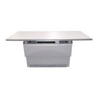
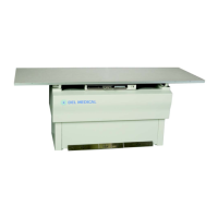
Details the physical dimensions and identifies major internal components of the generator.
Shows internal views of the generator subassemblies and their locations.
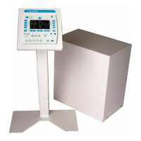
Shows the internal view of the console, including EPROM location.
Lists compatible X-ray tubes and AEC devices for the generator.
Provides contact information for customer support regarding X-ray generator operation.
States the compatibility statement for the generator.
Introduces the chapter's content on unpacking, positioning, and cabling the generator.
Details instructions for safely unpacking the generator and its components.
Provides steps for safely removing the generator's main cover.
Refers to Chapter 1 for identification and layout of major components.
Outlines requirements for placing the main cabinet and control console.
Explains the procedure for anchoring the generator to the floor if necessary.
General instructions for routing and securing cables to the generator.
Details connecting the console cable and specific steps for touchscreen consoles.
Shows connector designations and highlights connection warnings.
Describes the optional hand switch and its pin assignments for console connection.
Details stator and thermal switch connections to the H.V. auxiliary board.
Provides instructions and warnings for connecting the main power lines.
Covers the connection of high tension cables to the HT tank.
Specifies requirements for grounding the X-ray tube housing.
Details compatibility information for low speed starter tubes.
Explains how to set line voltage taps on auxiliary transformers for correct operation.
Explains how to set voltage taps for 400/480V generators based on line voltage.
Outlines steps to measure and verify various voltages after initial power-up.
Describes the procedure for calibrating the tube's mA output automatically.
Lists final checks to be performed before placing the generator into service.
Introduces chapter content on generator interfacing, programming, and related functions.
Covers wiring requirements for generator inputs and outputs.
Details the types and logic conditions for generator input signals.
Lists Bucky and auxiliary power outputs from the generator.
Provides a simplified schematic illustrating generator inputs and outputs.
Explains how to program and calibrate the generator via console or software.
Details steps to access the generator programming mode via the console.
Outlines the structure and options within the Generator Setup menu.
Introduces the Utility menu for accessing date/time, error log, and statistics.
Explains how to set the generator's date and time via console or GenWare®.
Describes the utility for displaying and reviewing stored error messages.
Explains the Statistics utility for viewing tube exposure and generator counts.
Details console configuration menus for operating features and factory defaults.
Defines the APR Editor function and provides steps to enable/disable APR technique changes.
Introduces configuration options: tube, limits, receptor, and I/O setup.
Allows selection of the desired tube type and setting default limits.
Shows screens for default tube limits like speed, standby current, and anode heat.
Provides steps for setting tube limits like kW, kV, standby current, and max current.
Allows setting of generator output limits like maximum kW, mA, mAs.
Enables programming of image receptors, including AEC and field settings.
Allows programming of input and output states for room interface signals.
Enables programming of AEC parameters for each AEC channel.
Provides the procedure for performing automatic X-ray tube calibration.
Covers connecting and setting up the DAP printer.
Lists compatible DAP devices and necessary interconnect cables.
Details the DAP setup menus for configuration and testing of the DAP device.
Outlines the steps for calibrating the DAP meter using dose and area measurements.
Explains the Data Link function for computer communication and software utilities.
Introduces touchscreen specific functions and utilities.
Details steps to access the system utilities menu, including password entry.
Allows editing of APR parameters and techniques.
Covers procedures for backing up, restoring, and transferring APR data.
Explains how to set the date and time on the touchscreen console.
Allows changing receptor symbols for easier identification.
Covers configuring touchscreen settings like voice messaging, ports, and language.
Provides the procedure for calibrating the touchscreen interface.
Introduces AEC calibration and notes factory configuration for AEC chambers.
Details AEC exposure time limitations and film/screen response effects.
Explains AEC calibration ranges and the interplay of film speed, density, and output.
Outlines essential precalibration steps and provides a setup worksheet.
Provides a worksheet for gathering information required for AEC calibration.
Lists critical checks to perform before starting AEC calibration.
Illustrates AEC chamber installation, emphasizing insulation requirements.
Describes the solid-state AEC board, its assignments, and gain adjustments.
Details pin outs for connectors on the solid-state AEC board.
Explains jumper settings for swapping left/right fields and notes on noise reduction.
Describes AEC board assembly 737992, its input assignments, and gain adjustments.
Details pin outs for connectors and jumper functions on the AEC board.
Describes the ion chamber AEC board, its assignments, and gain/compensation adjustments.
Details pin outs for connectors on the ion chamber AEC board.
Describes AEC board assembly 737998, its input assignments, and gain adjustments.
Details pin outs for connectors and jumper functions for ion chamber AEC.
Provides safety notes before AEC calibration and lists required test equipment.
Lists all necessary test equipment for performing AEC calibration.
Details the procedure for calibrating AEC for table Bucky receptors.
Covers kV breakpoint calibration for film screens using GenWare®.
Provides detailed steps for table Bucky AEC calibration.
Explains the process for calibrating AEC density settings.
Displays the density setup menus for adjusting density calibration values.
Shows GenWare® interface for density calibration and provides notes on density steps.
Details the procedure for calibrating AEC for wall Bucky receptors.
Introduces acceptance testing to verify generator performance after installation.
Lists all necessary test equipment for performing generator acceptance tests.
Details tests for basic console functions like power, receptor selection, and exposure.
Details tests for basic console functions, including power, receptor selection, and exposure.
Verifies the operation of the low speed starter.
Covers tests for accuracy and consistency of kV, time, mA, and mAs output.
Outlines steps to verify AEC calibration after initial installation.
Refers to a supplement for HVL, linearity, and reproducibility testing procedures.
Introduces tests for verifying generator performance characteristics.
Details the setup required for performing dose measurement tests.
Explains how to calculate and measure exposure reproducibility.
Outlines the procedure and calculations for testing generator linearity.
Describes the method for evaluating Half Value Layer (HVL) using aluminum filters.
Introduces the chapter on troubleshooting, covering status messages and malfunctions.
Lists status messages and error codes to help diagnose generator issues.
Indicates the current status of the generator, like DAP ready or generator offline.
Identifies messages when an exposure exceeds programmed limits.
Details specific error codes, their problems, and recommended actions for correction.
Details errors related to exposure, AEC, tomography, calibration, and thermal limits.
Lists errors related to interlocks, communication, battery, calibration data, AEC, receptors, tubes, and KV.
Covers errors related to mode inhibition, enabling functions, generator data, AEC device feedback, filament current, and AEC fields/tubes.
Lists errors for power supply duty limit, DAP overflow/device/data, inverter failure, and interlock status.
Covers errors related to KV over voltage, anode/cathode mA faults, rotor issues, and calibration limits.
Solves erratic console behavior, often caused by electrical noise, by improving grounding.
Introduces the chapter on the recommended periodic maintenance schedule and safety precautions.
Provides a template for recording installation details and service history.
Outlines preventative maintenance tasks based on frequency (6 months, 12 months, etc.).
Details the procedure for checking and topping up the insulating oil level in the HT tank.
Provides guidelines for cleaning plastic surfaces and equipment safely.
Covers precautions and procedures for replacing EPROMs on console and generator boards.
Details the procedure for replacing the lithium battery in the console and generator.
Provides steps for removing and reinstalling the AEC board.
Explains the importance and procedure for conditioning/seasoning X-ray tubes.
Discusses end-of-life considerations, hazardous materials, and disposal warnings.
Introduces the chapter on the generator's theory of operation.
Explains the functional theory organized by block diagrams.
Details the power-on sequence and logic for the generator.
Explains the DC bus and power distribution circuits for different configurations.
Describes the generator's interface with room equipment and signals.
Explains the sequence and logic for initiating an X-ray exposure.
Details kV control, feedback mechanisms, and fault detection.
Explains the theory of filament drive and mA control circuits.
Describes the operational theory of the low speed starter.
Explains the theory of operation for the Dose Area Product (DAP) circuits.
Details the theory of serial communication between console and generator.
Explains the theory of operation for the Automatic Exposure Control (AEC) system.
Introduces the chapter listing spare parts for the CMP 200 X-ray generators.
Provides a list of recommended spare parts for the CMP 200 family.
Lists major components like boards, transformers, and assemblies with part numbers.
Lists fuse types, part numbers, and suggested quantities for various locations.
Details HV auxiliary board part numbers and jumper settings for voltage selection.
Introduces the chapter containing functional schematics for the CMP 200 X-ray generator.
Lists the index of functional schematics and notes AEC board part number source.
Schematic showing DC bus and power distribution for 1-phase units.
Schematic illustrating DC bus and power distribution for 3-phase 400/480V units.
Schematic showing DC bus and power distribution for 3-phase 208V units.
Schematic illustrating the generator's system power-on sequence and control logic.
Schematic showing room interface signals between the generator and auxiliary boards.
Schematic illustrating the X-ray exposure initiation and control logic.
Schematic detailing kV control, feedback loops, error amplifiers, and inverter drive signals.
Schematic illustrating filament reference voltage, current limit clamp, and control circuits.
Schematic of the low speed starter circuit and its connections.
Core schematic for the Automatic Exposure Control (AEC) system.
Schematic illustrating serial communication between console and generator.
Schematic of the DAP circuit and its connections.
Diagram showing interconnects between major generator subassemblies.