Do you have a question about the Del Medical EV-800 and is the answer not in the manual?
Provides installation, operation, and service information for the EV800 Elevating Table.
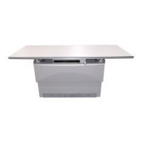
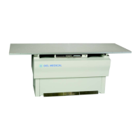
Details the EV800 table's design and suitability for general purpose radiography.
Presents diagrams and measurements for the EV800 table, including overall dimensions.
Illustrates required space around the table for safe operation, including buffer zones.
Lists technical specifications like voltage, current, weight, and certifications for the EV800 table.
Provides definitions for abbreviations used throughout the manual.
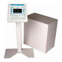
Shows images and descriptions of optional accessories available for the EV800 table.
Step-by-step guide for installing the EV800 table, covering tools, shipping, and unboxing.
Instructions for installing the Positive Beam Limitation (PBL) option on the EV800 table.
Procedure for installing the ion chamber option for automatic exposure control.
Steps to install the grid into the bucky assembly of the EV800 table.
Procedure to test the functionality of the collision avoidance switches on the EV800 table.
Instructions for inserting the cassette tray into the EV800 table's bucky.
Important safety guidelines to follow before operating the EV800 table to prevent injury.
Lists technical specifications relevant to the operation of the EV800 table.
Description of the various controls and pedals used to operate the EV800 elevating table.
Procedure for safely removing the cassette tray from the EV800 table.
Information on the emergency stop button's function and location for service technicians.
Schedule outlining recommended periodic maintenance tasks for the EV800 table.
Instructions for cleaning the external surfaces of the EV800 table and base.
Procedure for greasing the lift racks on the EV800 table to ensure smooth operation.
Guide for checking and adjusting the chain tension in the EV800 table's drive mechanism.
Overview of the maintenance and adjustment procedures covered in this chapter for the elevating table.
Common procedure for removing the front panels of the EV800 table, referenced in other procedures.
Step-by-step guide for replacing fuses on the EV800 table.
Procedure to manually override the drive motor for servicing the EV800 table.
Instructions for adjusting the table's mid-point height setting.
Procedure for testing and adjusting the collision avoidance switches.
Guide for changing the elevation restart mode from manual to automatic or vice versa.
Provides instructions for replacing most of the major assemblies on the elevating table.
Common procedure for removing the front panels of the EV800 table, referenced in other procedures.
Step-by-step instructions for replacing the main printed circuit board (PCB) of the EV800 table.
Procedure for replacing the foot treadle assembly on the EV800 table.
Instructions for replacing the drive motor assembly of the EV800 table.
Procedure for replacing a treadle switch on the EV800 table.
Instructions for replacing the left and right table lock mechanisms.
General instructions for replacing the height limit switches on the EV800 table.
Procedure for replacing the bucky lock mechanism on the EV800 table.
Instructions for replacing the collision avoidance switches on the EV800 table.
Procedure for replacing the transverse lock mechanisms on the EV800 table.
Detailed steps for disassembling and replacing the motor/gearbox assembly.
Overview of the troubleshooting chapter, divided into problem index and switch locations.
Index of common table problems and the corresponding page numbers for solutions.
Detailed charts listing problems, possible causes, and remedies for EV800 table malfunctions.
Diagram showing the location of treadle switches (S11-S14) on the EV800 table.
Diagram showing the location of limit switches (S101-S103) on the EV800 table.
Diagram showing the location of the bucky lock release switch (S301).
Diagrams illustrating the locations of various switches and locks (S304, S305).
Diagram showing the location of bucky coil locks (L301, L302).
List of available electrical schematic drawing numbers and their descriptions.
Table to match generator, tube stand, collimator, and wall stand models to the correct schematic drawing number.
Information on how to order replacement parts and accessories from Del Medical Inc.
Guide explaining how to navigate and use the illustrated parts list for ordering.
List of frequently ordered parts for the EV800 table with their corresponding part numbers.
Illustrated breakdown of the overall EV800 elevating table assembly.
Illustrated breakdown of the main control chassis assembly.
Illustrated breakdown of the drive frame assembly.
Illustrated breakdown of the motor reducer electrical assembly.
Illustrated breakdown of the foot treadle assembly.
List of available options and accessories for the EV800 elevating table with part numbers.
| Brand | Del Medical |
|---|---|
| Model | EV-800 |
| Category | Medical Equipment |
| Language | English |