4
INSTALLATION & OPERATION MANUAL
SONAC/120 LIQUID LEVEL SWITCH
DECEMBER 2008 REV 1.0
1.0 INTRODUCTION
1.1 Description
This device is a single point, electronic switch for ON-
OFF level control of liquids, at temperatures from -65ºF
(-54ºC) to 400ºF (204ºC) and pressures to 4000 psi.
Typical applications include, crude and rened petroleum,
hot asphalt, solvents, chemicals, liqueed air fractions, LPG,
LNG, and most other liquids
1.2 Principle of Operation
The SONAC/120 Switch is comprised of a sensor,
interconnecting cable and electronic control unit.
The sensor is a magnetostrictive device consisting of a
diaphragm, nickel drive tube, bias magnet, drive coil and
pickup coil. The sensor diaphragm is electronically driven
to oscillate at its resonant frequency with a high-velocity, low
amplitude motion. When the product level covers the sensor,
the diaphragm is dampened. This produces a change in the
output signal level from the sensor’s pickup coil. The control
amplier, which is in a regenerative feedback loop circuit
with the sensor, processes the signal change, and actuates
the output relay for the desired end function.
SELF-TESTING FEATURE: A logic network is included
in the feedback loop to “prove” the mechanical and electrical
integrity of the sensing circuit. If an open or short circuit
occurs in the sensor connecting cable, or control amplier,
the relay immediately transfers to the alarm condition.
1.3 Specications
Supply Voltage Normal Absolute Limits
115 VAC 95-135 VAC
230 VAC 190-270 VAC
or 12-24 VAC
12-24 VDC
Frequency, AC Power 50-60 Hz 45 Hz Minimum
Time Delay Standard, 50 ms to
Adjustable 15 seconds
Failsafe Switch selectable, High
or Low Level
Environmental Rating NEMA 4X, IP55
Control Unit
Temperature Amplier -40 to 75ºC
Sensor Temperature, Temperature and pressure
Pressure Rating limits vary with sensor
model. Consult SONAC/120
data sheet for specication
information.
Sensor Mounting/ 1” NPTM
Process Connection
Distance-Sensor to Control 150 ft (45.7M with PVC
Unit, Maximum
Insulated Cable (BLUE)
100ft (30.5M) with TFE
Insulated (WHITE)
Indicators Two, light emitting diodes (LED).
RED - Illuminated when product is
present at sensor
YELLOW - Illuminated when relay is
energized
Output Relay, DPDT 2 Form C Contracts
5 A at 120 VAC Non-Inductive
3 A at 240 VAC Non-Inductive
3 A at 24 VDC Non-Inductive
Shipping Weight Control: 5 Pounds (2.5 Kilograms)
Sensor: 1.6 Pounds (.68) Kilograms
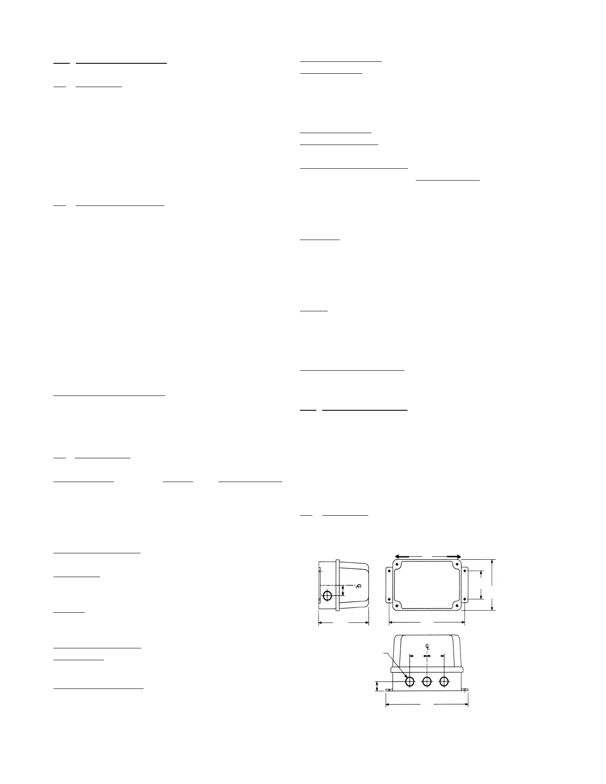
2.2 Mechanical
AMPLIFIER HOUSING
.875
(22.2)
2.00
(51)
6.000
(152.4)
1.062
(27)
8.625
(219)
2.00
(51)
3.00
(76.2)
9.375
(238)
1/2” Condult knockout
8.187
(208)
5.179
(131.5)
INSTALLATION DRAWING
NOTE: DIMENSIONS IN PARENTHESES DENOTE MILLIMETERS
2.0 INSTALLATION
2.1 Unpacking
Remove the system from the shipping carton and check the
nameplate model number against the packing list before
destroying any packing material. Remove plastic protective
closures from sensor
 Loading...