INSTALLATION & OPERATION MANUAL
SONAC/120 LIQUID LEVEL SWITCH
DECEMBER 2008 REV 1.0
7
2.3 Electrical Installation
All electrical connections are made to the terminal strip in
the enclosure. Remove the cover, and the plug-in control
board, and wire the unit to power and control conduits in
accordance with applicable electrical codes. Refer to the
wiring diagram (2.3.1) for proper connections.
Do not substitute other cable for the special cable supplied by
DELAVAN for connection from the control unit to the sensor.
If the distance between the sensor and control exceeds the
stated cable length, consult the factory for specic installation
instructions.
DO NOT INSTALL, OR REMOVE THE PRINTED
CIRCUIT CARD WITH SYSTEM OR RELAY
CIRCUITS ENERGIZED, SERIOUS DAMAGE CAN
OCCUR TO CARD CONNECTIONS.
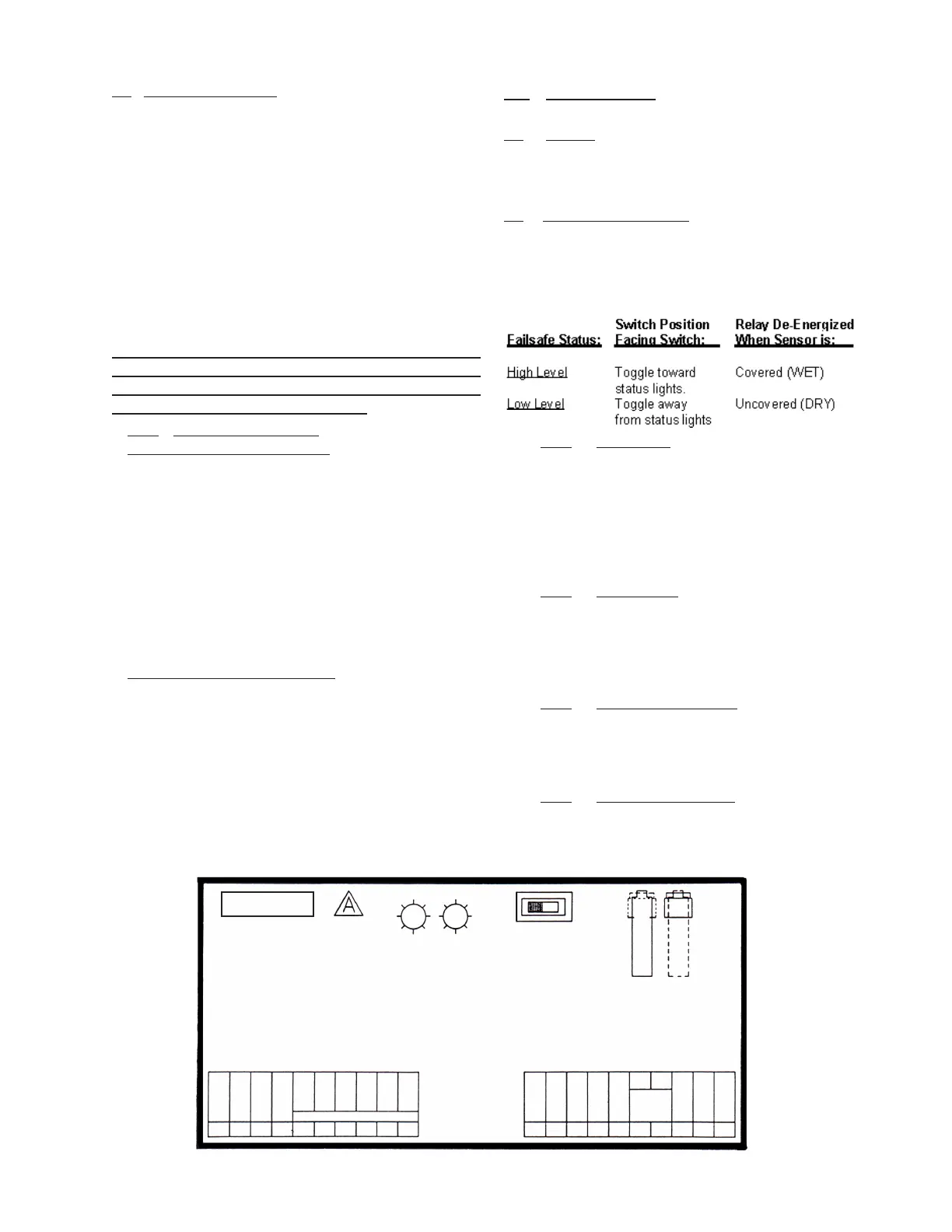
2.3.1 Terminal Designations:
Class I (Line Voltage) Terminals
1) Chassis Ground
2) Line Neutral
3) Line 115 VAC
4) Line 230 VAC
5) First set of Contacts N.C. (Power OFF)
6) Common
7) N.O.
8) Second set of Contacts N.C. (Power OFF)
9) Common
10) N.O.
Class II (Low Voltage) Terminals
11) Sensor (Black Lead)
12) Not Used
13) Sensor Shield (Bare Wire)
14) Not Used
15) Not Used
16) Low Voltage Input +24 v AC or DC
17) Low Voltage Input -
18) Not Used
19) Not Used
20) Sensor (White or Clear Lead)
3.0 OPERATION
3.1 General
3.2.1 Time Delay
A 20 turn potentiometer is furnished to adjust the time
delay between the sensor change of state (wet to dry
or dry to wet) and the relay actuation. The time delay
range is 50 milliseconds to approximately 15 seconds
maximum delay on and off.
3.2.2 Gain Control
A 20 turn potentiometer is furnished to match the
amplier gain with the sensor. CW rotation increases
the gain.
3.2.3 Liquid Level Indicator
A RED LED is illuminated when the product is pres-
ent at the sensor.
3.2.4 Relay Status Indicator
A YELLOW LED is illuminated when the relay is
energized.
3.2 Controls and Indicators
The Failsafe Switch determines the relay state when the
liquid is present. Failsafe high or failsafe low does not
indicate the physical location of the sensor installed in the
vessel.
This section contains the calibration and operational
information for the SONAC/120 Switch
3
109
8
765
4
21
20
191817
1615
14
13
1211
ASSEMBLY NO: 42854
I N S T R . M A N U A L :
42858
RELAY CONTACTS
LOW
FAIL
SAFE
RELAY
FUNCTION
HIGH
FAIL
SAFE
SENSOR
STATUS
RELAY
STATUS
SONAC
NO
C
NC
NO
C
NC
230 VAC
115 VAC
GAIN
SENSOR
WHITE
LOW
VOLT
INPUT
SENSOR
SHIELD
TIME DELAY
SENSOR
BLACK
 Loading...