Starting System
Page 4A-6 90-864260200 AUGUST 2009
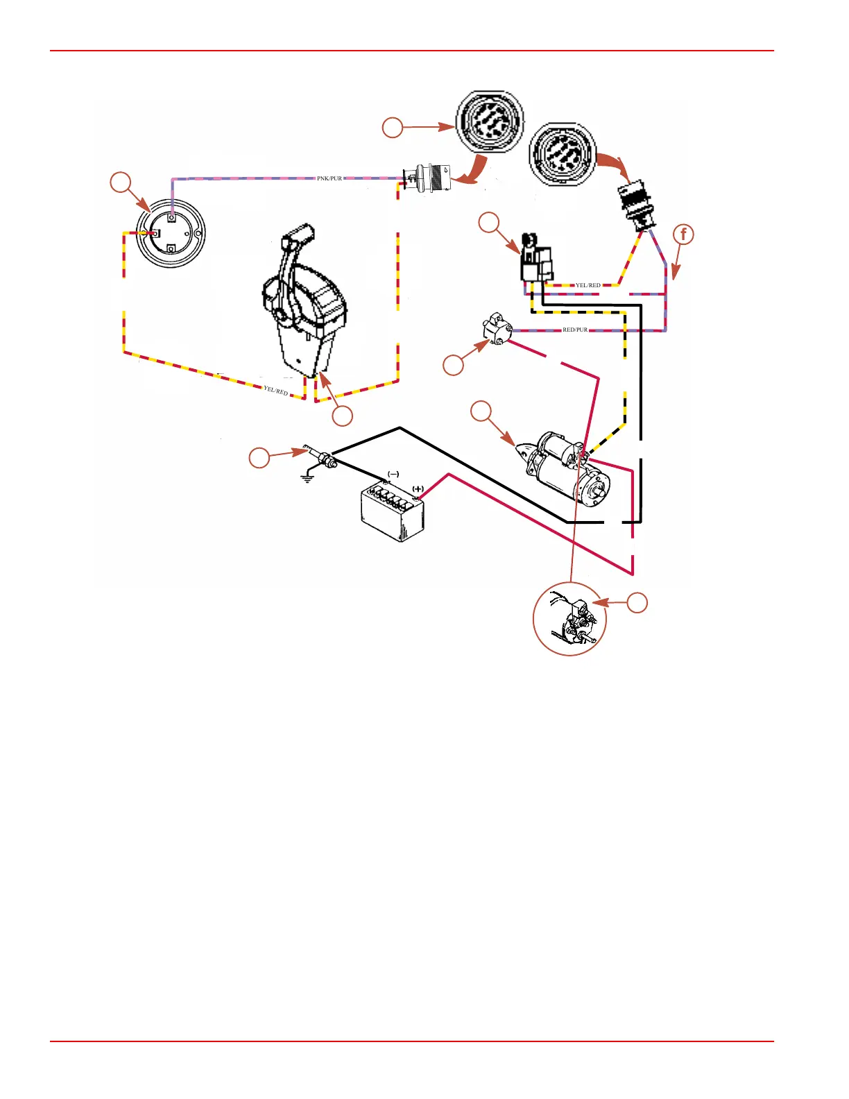
14‑pin Starting System Electrical Diagram
a - Ignition switch
b - Harness plug
c - Starter solenoid
d - Circuit breaker
e - Starter motor
f - Wire junction
g - Neutral safety switch
h - 90‑amp fuse
i - Engine ground (–)
This is a general description of the positive current flow from the battery through the starting system until the starter motor cranks.
NOTE: Ensure that all connections are tight and have the required resistance.
• Battery to the solenoid switch on the starter (RED battery cable).
• Solenoid switch to the circuit breaker (RED).
• Circuit breaker to the wire junction (RED/PPL).
• Wire junction to the wiring harness plug terminal 6 (RED/PPL).
• Ignition switch terminal "C" to the neutral start switch (YEL/RED). Neutral start switch must be at neutral position.
Battery Cable Size for MerCruiser Models
IMPORTANT: Only use copper battery cables. Do not use aluminum cables for any marine installations.
B
S
I
25316
PNK/PUR
YEL/RED
YEL/RED
YEL/RED
YEL/RED
YEL/RED
RED/PUR
YEL/BLK
RED
RED/PUR
RED
BLK
BLK
b
d
e
f
g
h
i
a
c