Starting System
90-864260200 AUGUST 2009 Page 4A-9
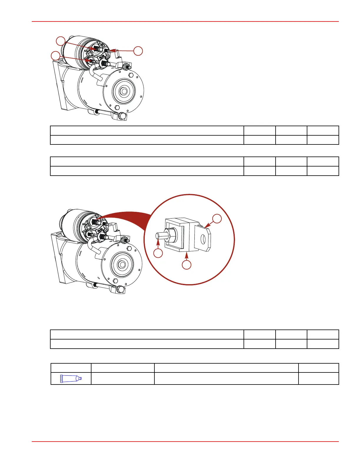
2. Connect the YELLOW/RED wire to the switch "S" terminal. Tighten the terminal nut to specification.
Starter electrical connections
a - Switch terminal, (S)
b - Positive battery terminal (+)
c - Resistor terminal (R)
Description Nm lb‑in. lb‑ft
Switch terminal (S) nut 2 18 –
3. Connect the positive (+) battery cable and the 90 amp fuse to the battery terminal. Tighten the terminal nuts to specification.
Description Nm lb‑in. lb‑ft
Battery terminal nut 9.5 84 –
4. Connect the ORANGE wire and the RED wire to the post on the 90 amp fuse that is installed to the starter positive (+) battery
terminal. Tighten terminal nut securely.
a - Starter terminal
b - Insulator
c - Positive (+) battery connection
NOTE: The back of the fuse is an insulator.
NOTE: The PURPLE/YELLOW wire is the 12 volt battery positive (+) to the electronic fuel pump while the engine is in starting
mode.
5. Carbureted Models: Connect the PURPLE/YELLOW wire to the resistor "R" terminal. Tighten the terminal nut to specification.
Description Nm lb‑in. lb‑ft
Resistor (R) terminal nut 2 18 –
6. Coat all terminal with sealant.
Tube Ref No.
Description Where Used Part No.
25
Liquid Neoprene Electrical connections 92- 25711 3
7. Install the battery cable boot, if equipped.
8. Connect the positive (+) battery cable to the positive (+) battery terminal and tighten the cable clamp.
9. Connect the negative (‑) battery cable to the negative (‑) battery terminal and tighten the clamp.