Do you have a question about the Delixi CDW3 Series and is the answer not in the manual?
Visual indicators for danger, notice, and prohibition.
Details on the open state of the circuit breaker.
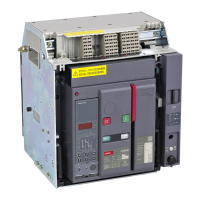
General information about the circuit breaker.
Explains how to read the circuit breaker's nameplate and data.
Provides dimensions and weights for different models.
Diagrams and labels for the circuit breaker's internal components.
Step-by-step guide for debugging the circuit breaker.
Instructions for operating the drawer seat mechanism.
Guidelines for safe handling and transportation of the circuit breaker.
Methods for properly carrying the circuit breaker and its components.
Specific instructions for lifting and carrying the drawer seat.
Introduction, tools, requirements, and basic installation steps.
Guidance on busbar connection and required safety distances.
Tables for busbar sizing, bolt configuration, and drilling.
Dimensions and fixation details for 1600N&H draw-out and fixed types.
Diagrams for various back connection types on 1600N&H models.
Dimensions and fixation details for 1600N&H fixed 3P/4P types.
Diagrams for various back connection types on 1600N&H fixed models.
Dimensions and details for 2000N&H draw-out and fixed types.
Dimensions and details for 2000N&H fixed 3P/4P types.
Dimensions and details for 2500N&H draw-out and fixed types.
Dimensions and details for 2500N&H fixed 3P/4P types.
Dimensions and details for 3200N&H draw-out and fixed types.
Dimensions and details for 3200N&H fixed 3P/4P types.
Dimensions and details for 4000N&H draw-out types.
Diagrams for 4000N&H and 4000A draw-out/fixed back connections.
Dimensions and details for 4000N&H fixed types.
Diagrams for 4000N&H and 4000A fixed back connections.
Dimensions and details for 6300N draw-out types.
Specific details for 4000N draw-out back connections.
Procedures for installing various circuit breaker accessories.
Steps for connecting the secondary circuit wiring for various models.
How to install leakage, n-phase, and grounding transformers.
Dimensions of optional N-phase external transformers.
Dimensions for leakage, grounding, power, and signal conversion modules.
Complete wiring diagram for secondary circuits.
Wiring diagram for iTR326H controller's secondary circuit.
Overview of the iTR326 series electronic trip units.
Visuals and functional descriptions of trip units.
Explains indicators and buttons for the iTR326 unit.
Explains indicators and buttons for the iTR326A unit.
Explains indicators and buttons for the iTR326H unit.
General protection features of the electronic trip unit.
Details on inverse time limit and timing limit features.
Action thresholds and timing for overload protection.
Action thresholds and timing for short circuit protection.
Action thresholds for instantaneous short circuit protection.
Action thresholds and timing for earth fault protection.
Default protection settings for the intelligent controller.
Navigation menu for different trip unit models.
Menu operations for iTR326 unit.
Menu operations for iTR326A unit.
Menu operations for iTR326H unit.
How to operate the iTR326A unit.
Display modes and indicators on the iTR326A unit.
Details on ammeter display modes and operation.
How to set and display parameters.
Guide to setting user-configurable parameters on iTR326A.
How to operate the iTR326H unit.
Initial display interface of the iTR326H unit.
Accessing measurement data on the iTR326H.
Accessing system parameter settings on the iTR326H.
Setting protection parameters on the iTR326H.
Accessing historical data and maintenance logs.
Table of technical specifications for CDW3 circuit breakers.
Identifies and describes key accessories for the circuit breaker.
Details on the MX release coil function.
Details on the XF closing coil function.
Details on the MN undervoltage release.
Details on the MNR undervoltage delay coil.
Details on the MCH motor operating mechanism.
Types and functions of indicating contacts.
Function of auxiliary switches for status monitoring.
Function of PF contact for closing preparation.
Function of SWT1 for fault trip indication.
Function of remote reset contact.
Function of three-position indicating contacts.
Types and functions of locking mechanisms.
Use of padlocks for draw frame security.
Function of opening locks.
Mechanism for locking drawer positions.
Function of door interlocks for safety.
Types of mechanical interlocks.
Use of button locks for preventing misoperation.
Protective features and components.
Features of the door frame.
Function of interphase partitions.
Use of safety baffles for protection.
Specifics of safety damper locks.
Function of secondary wiring terminal covers.
List and description of controller accessories.
Details on N-phase external transformers.
Details on grounding transformers.
Details on leakage transformers.
Details on power converters.
Details on signal conversion modules.
Accessories for connections.
Accessories related to configuration.
Environmental conditions for operation and installation.
Schedule and methods for regular maintenance.
Intervals and modes for routine inspections.
List of parts requiring replacement based on usage.
Detailed steps for performing maintenance tasks.
Common faults, causes, and solutions.
List of commonly needed replacement parts.
Graphs showing protection trip curves.
Trip curves for three-stage protection settings.
Trip curves for earth fault protection.
Table to assist in selecting the correct model.
Table detailing standard and optional configurations.
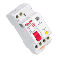
| Number of Poles | 1P, 2P, 3P, 4P |
|---|---|
| Operating Temperature | -5°C to +40°C |
| Rated Voltage (Ue) | 230/400V AC |
| Rated Impulse Withstand Voltage (Uimp) | 4kV |
| Rated Voltage | 230/400V AC |
| Breaking Capacity | 6kA |
| Standard | IEC 60898-1 |
| Rated Insulation Voltage (Ui) | 500V |
| Mounting | DIN Rail |
| Mechanical Life | 20, 000 operations |
| Electrical Life | 10, 000 operations |
| Tripping Characteristics | C |
| Rated Current | 6A - 63A |