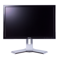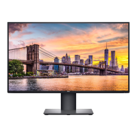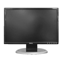
Do you have a question about the Dell 2005FPW - UltraSharp - 20.1" LCD Monitor and is the answer not in the manual?
Warnings about critical components and electrical shock risks during servicing.
Procedures for safely mounting, handling, and protecting the LCD module from damage.
Diagram for measuring leakage current using an AC voltmeter and ground.
General guidelines for performing service operations safely and correctly.
Procedures to prevent damage to sensitive electronic components from static electricity.
Guidelines for soldering and replacing various electronic components like ICs, transistors, diodes, fuses, and resistors.
Method for repairing damaged copper patterns at IC connections using jumper wires.
Method for repairing defective copper patterns at non-IC connections with jumper wires.
Detailed table of video and sync timing parameters for various display modes.
Detailed, step-by-step instructions with images for safely removing the rear cabinet.
Visual representation of the monitor's main components and their signal flow.
Explanation of the part responsible for video signal conversion and data transmission.
Description of the power regulation and distribution circuitry within the monitor.
Detailed description of each functional block within the power supply unit.
Guide for setting up and managing Extended Display Identification Data (EDID) using provided software.
Details of the Service OSD menu options for adjustment and configuration.
Diagnostic steps and checks for troubleshooting when the monitor does not power on.
Troubleshooting steps for cases where the screen is blank or OSD is not visible.
Diagnostic flow for no raster/OSD issues related to the GM1501CF chipset.
Steps for diagnosing and resolving issues related to the Digital Picture Mode (DPM).
Diagram illustrating the connection points and wiring harness of the monitor.
Visual representation of the monitor disassembled into its component parts.
Comprehensive list of parts with their reference numbers, part numbers, and descriptions.
Detailed listing of all replaceable components with their part numbers and specifications.
Circuit diagrams illustrating the connections and pinouts for various connectors.
Detailed circuit diagram for the TW9905 IC, showing its internal connections and external components.
Circuit diagram for the GM1601 Scaler IC, detailing its functional blocks and connections.
Circuit diagrams illustrating the power supply and connector interfaces of the monitor.
Circuit diagram for the USB hub functionality, showing its controller and connected components.
Diagram showing the circuitry for the monitor's input buttons and LEDs.
Circuit diagram detailing the USB interface, including D-ports and related components.


