Installation procedure for 2x Canbus uFM
module
About this task
Installation requires the removal of WiFi, as well as COM3 and COM4 ports. The 4-port COM cable will be replaced with an
included dual-port COM cable.
Table 10. Expansion module packing list
Item Quantity Notes
Screw M3 x 4L 8 Torque required: 4.0 kgf.cm
Standoff H4 8 Torque required: 4.5 kgf.cm
Screw M2.5 x 6L 2 Torque required: 3.0 kgf.cm
Nut M3 4 Torque required: 4.0 kgf.cm
Cable tie 2 -
Rubber cap 2 -
Sheet metal I/O panel 1 -
Canbus mPCIe 1 -
Dual-port COM cable 1 -
Cable 2 -
Steps
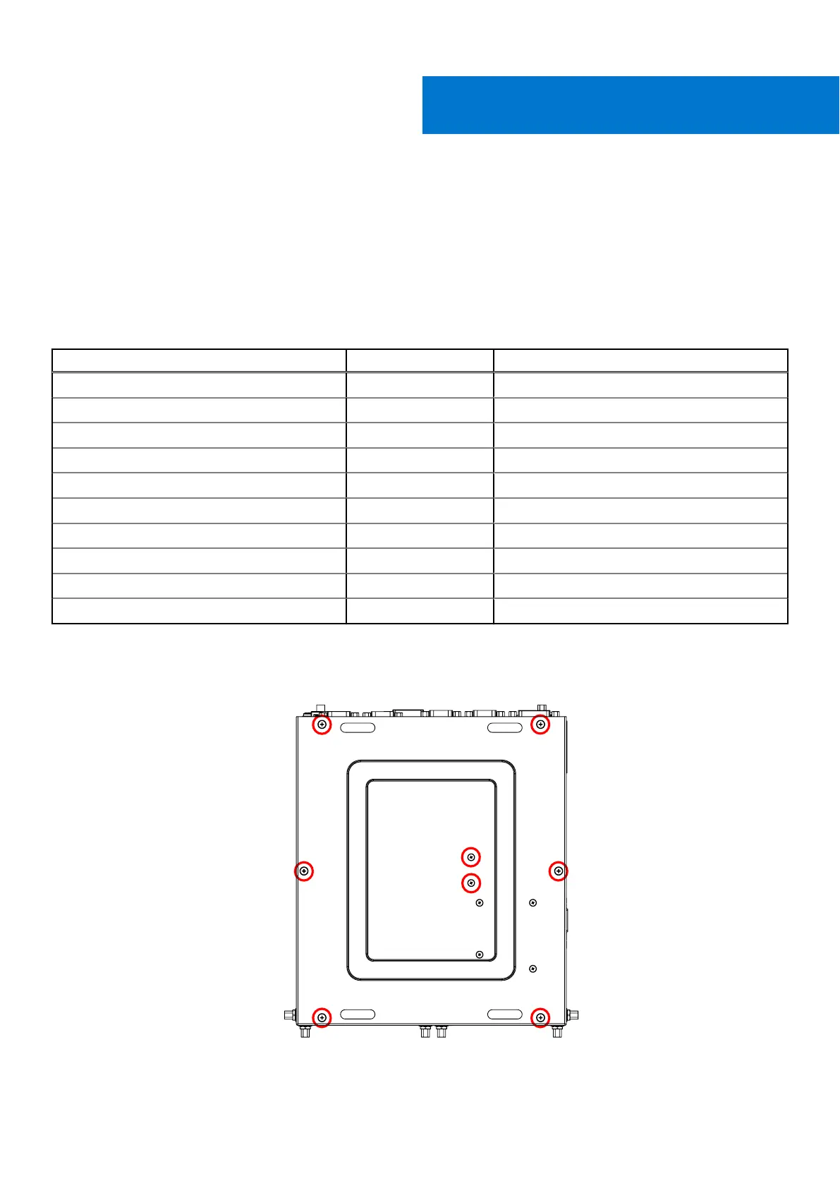
1. Remove the eight screws from the bottom panel of the EGW-5200, as shown in the following figure, and remove the bottom
panel.
Figure 81. Bottom panel screw locations
VI
Installation procedure for 2x Canbus uFM module 47
 Loading...