About this task
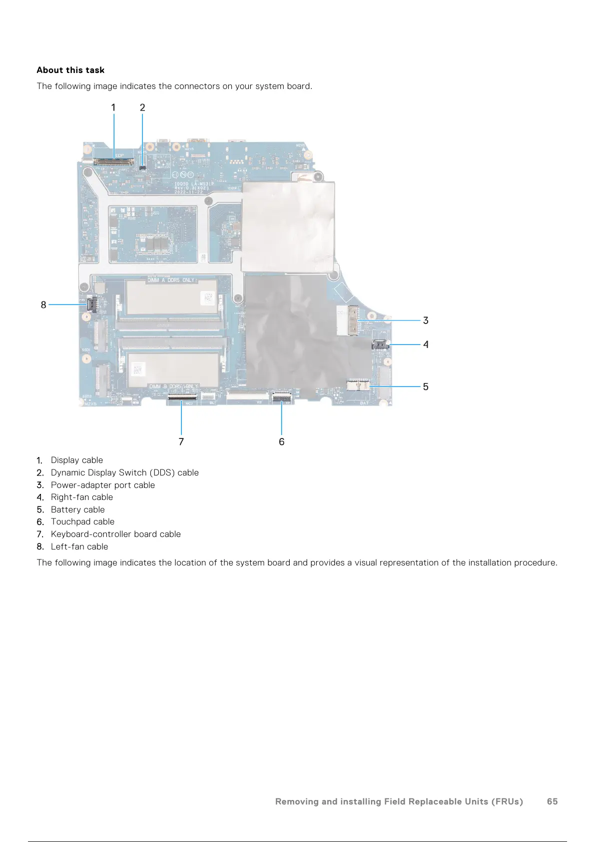
The following image indicates the connectors on your system board.
1. Display cable
2. Dynamic Display Switch (DDS) cable
3. Power-adapter port cable
4. Right-fan cable
5. Battery cable
6. Touchpad cable
7. Keyboard-controller board cable
8. Left-fan cable
The following image indicates the location of the system board and provides a visual representation of the installation procedure.
Removing and installing Field Replaceable Units (FRUs)
65
66 / 102 65 / 100 66 / 102