Installing the fan and heat-sink assembly
Prerequisites
If you are replacing a component, remove the existing component before performing the installation procedure.
About this task
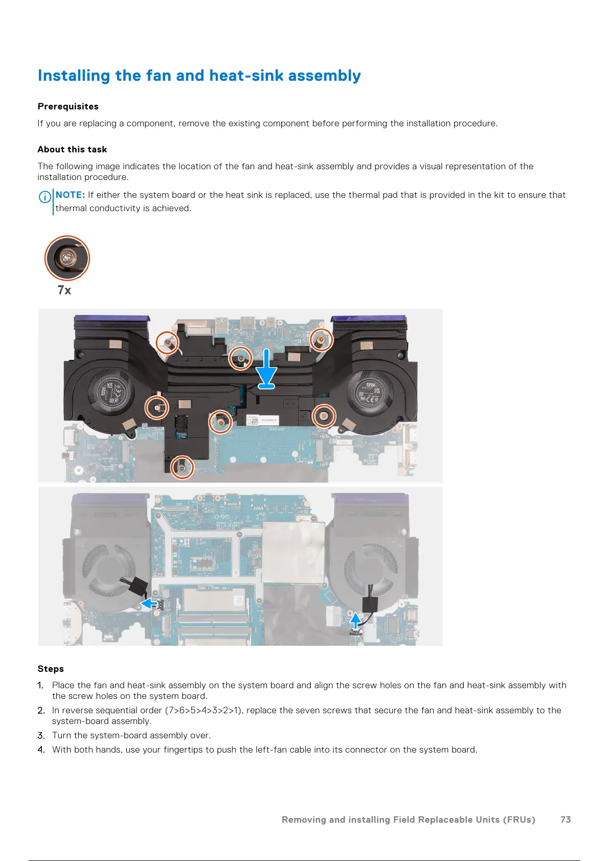
The following image indicates the location of the fan and heat-sink assembly and provides a visual representation of the
installation procedure.
NOTE: If either the system board or theheat sinkis replaced, use the thermal pad that is provided in the kit to ensure that
thermal conductivity is achieved.
Steps
1. Place the fan and heat-sink assembly on the system board and align the screw holes on the fan and heat-sink assembly with
the screw holes on the system board.
2. In reverse sequential order (7>6>5>4>3>2>1), replace the seven screws that secure the fan and heat-sink assembly to the
system-board assembly.
3. Turn the system-board assembly over.
4. With both hands, use your fingertips to push the left-fan cable into its connector on the system board.
Removing and installing Field Replaceable Units (FRUs)
73
74 / 102 73 / 100 74 / 102