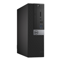
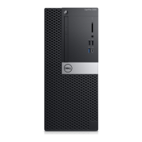
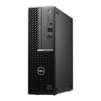
Feature Specification
Password clear jumper 2-pin connector
RTC reset jumper 2-pin connector
Internal speaker 4-pin connector
Intruder connector 3-pin connector
Power connector One 8-pin(for PSU), one 4-pin(for CPU), one 8-pin for
SATA power
Table 16. Controls and lights
Feature Specification
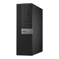
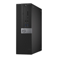
Front of the computer
Power button light White light — Solid white light indicates power-on state;
blinking white light indicates sleep state of the
computer.
Drive activity light White light — Blinking white light indicates that the
computer is reading data from or writing data to the
hard drive.
Back of the computer
Link integrity light on integrated network
adapter
• Green — a 10 Mbps connection exists between the
network and the computer.
• Green — a 100 Mbps connection exists between the
network and the computer.
• Orange — a 1000 Mbps connection exists between
the network and the computer.
• Off (no light) — the computer is not detecting a
physical connection to the network.
Network activity light on integrated
network adapter
Yellow light — A blinking yellow light indicates that
network activity is present.
Power supply diagnostic light Green light — The power supply is turned on and is
functional. The power cable must be connected to the
power connector (at the back of the computer) and the
electrical outlet.
Table 17. Power
NOTE: Heat dissipation is calculated by using the power supply wattage rating.
Power Wattage Maximum Heat
Dissipation
Voltage
240 W 819.00 BTU/hr 100 VAC to 240 VAC, 50 Hz
to 60 Hz, 4A/2A
Coin cell battery 3 V CR2032 lithium coin cell
43
 Loading...
