DELL™ OPTIPLEX™ 960 TECHNICAL GUIDE
9
BACK PANEL CONNECTORS
1
PS/2 Mouse Connector 8 Line-out Connector
2 Parallel Connector 9
Line-in/Microphone
Connctor
3 Serial Connector 10 USB 2.0 Connectors (6)
4 Link Integrity Light 11 VGA Connector
5
Network Adapter
Connector
12 eSATA Connector
6 Network Activity Light 13 DisplayPort Connector
7
Wireless Network
Adapter (optional)
14
PS/2 Keyboard
Connector
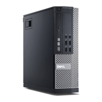
SMA LL FORM F ACT OR C O M P UT E R (SF F) VI EW ( CO NT. )
SYSTEM BOARD
1
Fan Connector
(FAN_CPU)
12 Serial Port Connector
2
Processor Connector
(CPU)
13
Intrusion Switch
Connector
(INTRUDER)
3
Processor Power
Connector
(12VPOWER)
14
Front Panel Thermal
Sensor Cable
Connector
4
Memory Module
Connectors (DIMM_1,
DIMM_2, DIMM_3,
DIMM_4)
15
Real Time Clock Reset
(RTCRST)
5
Password Jumper Pins
(PSWD)
16
PCI Express x16
Connector (SLOT1)
6
SATA Drive
Connectors (3)
17
PCI Connector
(SLOT2)
7
Internal (FlexBay)
USB Connector
18
Battery Socket
(BATTERY)
8
Service Mode
Jumper Pins
19
Hard Drive Fan
Connector (FAN_HDD)
9
Front-panel Connector
(FRONTPANEL)
20
Floppy Drive
Connector (DSKT)
10
Power Connector
(POWER)
21 Internal Speaker
11
PSU Thermal Sensor
Connector
22
Connector for Optional
Wireless Card