EasyManuals Logo

Dell PowerEdge PDU Managed LED User Manual

Dell PowerEdge PDU Managed LED
145 pages
To Next Page IconTo Next Page
To Previous Page IconTo Previous Page
Page #118 background imageLoading...
Page #118 background image
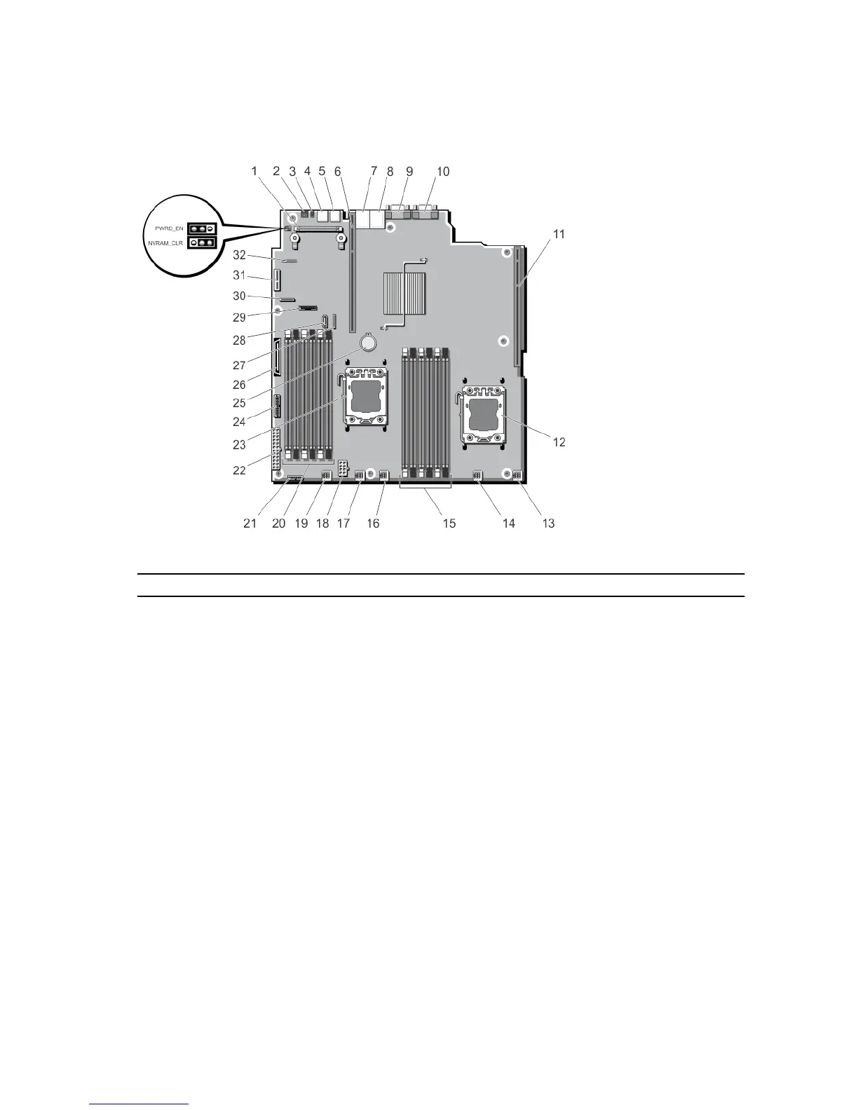
System Board Connectors
Figure 61. System Board Jumpers and Connectors
Item Connector Description
1 INT_STORAGE Storage controller card connector
2 ID_BTN System identification button
3 CMA_JACK System identification connector
4 USB 2 USB connector
5 USB 1 USB connector
6 IO_RISER2 Riser 2 connector
7 NIC2 Network connector
8 NIC1 Network connector
9 VGA Video connector
10 COM Serial connector
11 IO_RISER1 Riser 1 connector
12 CPU2 Processor socket 2
13 FAN6 Cooling fan connector
14 FAN5 Cooling fan connector
118

Table of Contents

Other manuals for Dell PowerEdge PDU Managed LED

Questions and Answers:

Question and Answer IconNeed help?

Do you have a question about the Dell PowerEdge PDU Managed LED and is the answer not in the manual?

Dell PowerEdge PDU Managed LED Specifications

General IconGeneral
BrandDell
ModelPowerEdge PDU Managed LED
CategoryServer
LanguageEnglish

Related product manuals