EasyManuals Logo

Dell PowerEdge PDU Managed LED User Manual

Dell PowerEdge PDU Managed LED
145 pages
To Next Page IconTo Next Page
To Previous Page IconTo Previous Page
Page #44 background imageLoading...
Page #44 background image
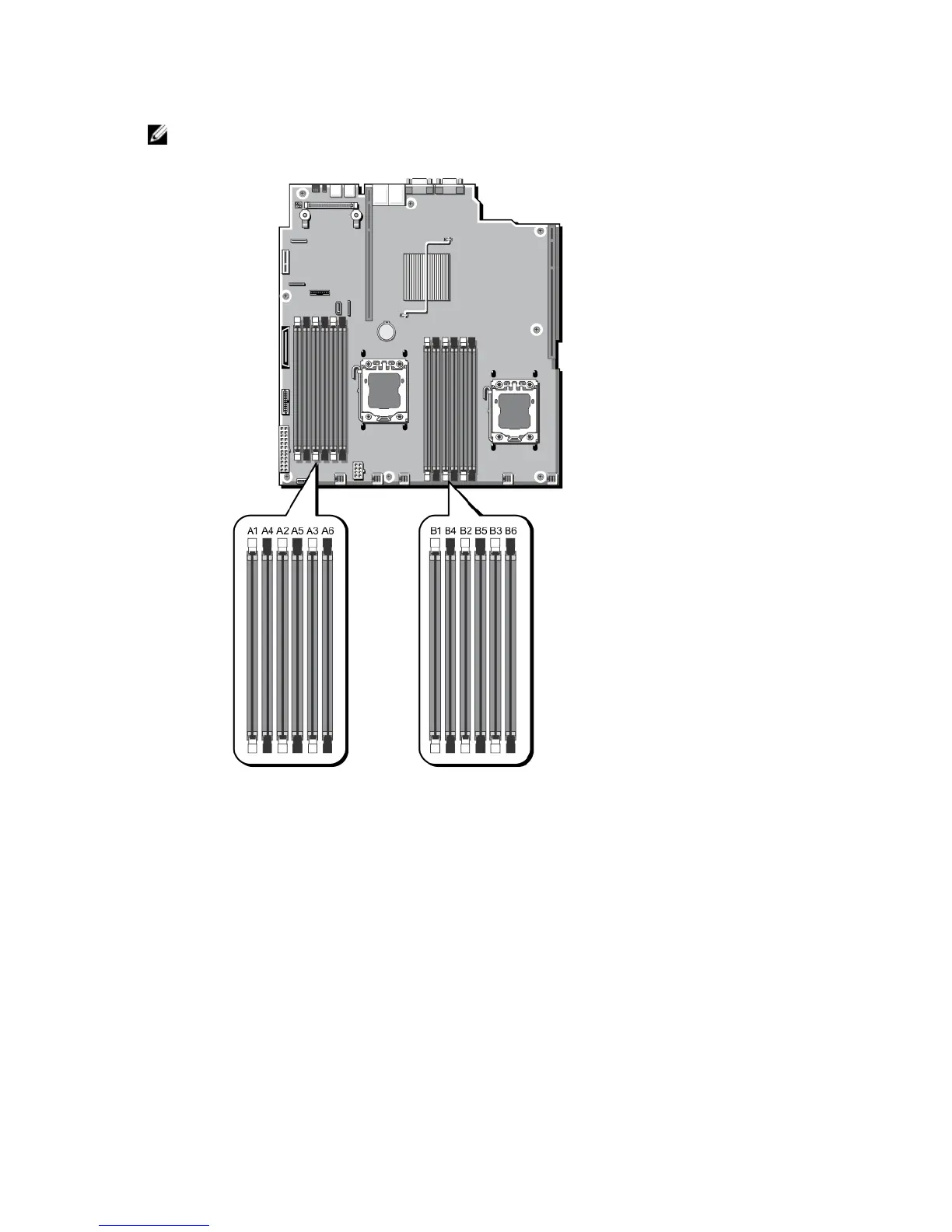
NOTE: DIMMs in sockets A1 to A6 are assigned to processor 1 and DIMMs in sockets B1 to B6 are assigned to
processor 2.
Figure 14. Memory Socket Locations
Memory channels are organized as follows:
Processor 1 channel 1: memory sockets A1 and A4
channel 2: memory sockets A2 and A5
channel 3: memory sockets A3 and A6
Processor 2 channel 1: memory sockets B1 and B4
channel 2: memory sockets B2 and B5
channel 3: memory sockets B3 and B6
44

Table of Contents

Other manuals for Dell PowerEdge PDU Managed LED

Questions and Answers:

Question and Answer IconNeed help?

Do you have a question about the Dell PowerEdge PDU Managed LED and is the answer not in the manual?

Dell PowerEdge PDU Managed LED Specifications

General IconGeneral
BrandDell
ModelPowerEdge PDU Managed LED
CategoryServer
LanguageEnglish

Related product manuals