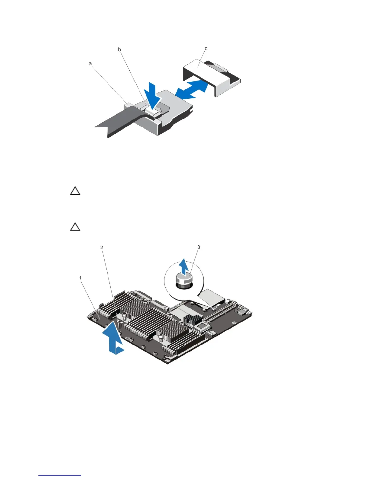
a. mini SAS cable connector
b. metal tab
c. connector on the system board
6. Disconnect all other cables from the system board.
CAUTION: Take care not to damage the system identification button while removing the system board from
the chassis.
7. Grasp the system-board holder, lift the blue release pin, slide the system board toward the front of the system, and
lift the system board out of the chassis.
CAUTION: Do not lift the system board assembly by grasping a memory module, processor, or other
components.
Figure 54. Removing and Installing the System Board
1. system board
2. system-board holder
3. release pin
99
 Loading...


