Do you have a question about the Dell PowerEdge R6625 and is the answer not in the manual?
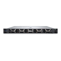
Details the layout and components visible on the front of the server.
Details the ports, panels, and slots located on the rear of the server.
Provides an internal view of system components and their locations.
Explains how to find the system's unique identifier for support and tracking.
Describes the location and content of the system information label.
Provides information on selecting and fitting rails for rack installation.
Details the physical measurements of the server chassis.
States the weight of the server based on its configuration.
Outlines the capabilities and types of processors supported by the system.
Details the specifications for the power supply units (PSUs) used in the system.
Describes the types and specifications of cooling fans used in the system.
Lists the operating systems compatible with the PowerEdge R6625 server.
Specifies the type of system battery used in the server.
Details the specifications for expansion card risers and supported PCIe slots.
Outlines the memory types, capacities, and speeds supported by the system.
Lists the supported storage controller cards for the system.
Describes the types of drives supported by the PowerEdge R6625 system.
Details the specifications for the various ports and connectors on the system.
Describes the video controller and supported resolutions.
Specifies the operating conditions such as temperature, humidity, and altitude.
Refers to documents providing diagrams for system setup.
Provides information on selecting and installing rack rails and cable management solutions.
Outlines the steps for initial system setup and configuration.
Describes how to access and use the system setup utility for BIOS and iDRAC configuration.
Explains the capabilities of the Dell Lifecycle Controller for system management.
Describes the Boot Manager option for selecting boot utilities.
Explains how to use PXE boot for network configuration.
Lists the essential components required for the system to power on.
Describes the process of validating system configuration and reporting errors.
Provides essential safety precautions to follow before performing any system operations.
Outlines the necessary steps to take before opening the system for maintenance.
Details the steps to perform after completing maintenance inside the system.
Lists the tools required for system component removal and installation.
Describes the optional front bezel and its features, including the LCD panel.
Provides instructions for removing and installing the system cover.
Describes the right and left control panels and their removal/installation.
Details the removal and installation procedure for the VGA module.
Explains how to remove and install the air shroud for proper cooling.
Provides instructions for removing and installing cooling fan modules.
Covers the removal and installation of drive blanks and carriers.
Describes the supported drive backplane options.
Explains the importance and methods of effective cable routing within the system.
Details the procedure for removing and installing the front PERC module.
Provides instructions for removing and installing the rear drive module.
Outlines system memory guidelines and installation procedures.
Details the removal and installation of the processor and heat sink.
Covers expansion card installation guidelines and riser configurations.
Describes the removal and installation of the optional serial COM port.
Covers the removal and installation of the BOSS N1 module and its components.
Details the removal and installation of the M.2 SSD module on the BOSS-N1 adapter card.
Provides instructions for replacing the system battery.
Describes the removal and installation of the optional internal USB card.
Covers the removal and installation of the intrusion switch module.
Details the removal and installation of the optional OCP card.
Provides instructions for removing and installing power supply units (PSUs).
Details the upgrading and replacement of the Trusted Platform Module (TPM).
Covers the removal and installation of the system board.
Details the removal and installation of the LOM card and rear I/O board.
Describes the removal and installation of the tube clip.
Refers to documents providing diagrams for system setup.
Provides information on selecting and installing rack rails and cable management solutions.
Outlines the steps for initial system setup and configuration.
Ensures the necessary tool (QR code scanner) is available for accessing information.
Provides steps on how to use the Quick Resource Locator (QRL).
Identifies and describes the various connectors on the system board.
Explains the system board jumper settings and their functions.
Provides instructions on how to disable system and setup passwords.
Explains the system status indicated by the front panel LEDs.
Describes the codes for system health and system ID indicators.
Explains the indicator codes for the optional iDRAC Quick Sync 2 feature.
Describes the LED indicator codes for the iDRAC Direct port.
Details the LCD panel features, status, and error messages.
Explains the indicator codes for the Network Interface Controller (NIC).
Describes the indicator codes for the power supply units (PSUs).
Explains the indicator codes for the drives.
Introduces the Dell Embedded System Diagnostics (ePSA) for hardware testing.
Explains how to run diagnostics using the Boot Manager if the system does not boot.
Details how to run embedded system diagnostics using the Dell Lifecycle Controller.
Introduces the Dell Embedded System Diagnostics (ePSA) for hardware testing.
Explains how to run diagnostics using the Boot Manager if the system does not boot.
Provides information on product disposal and recycling services.
Explains how to contact Dell for support and service options.
Describes how to use the Quick Resource Locator (QRL) for system information.
Explains the benefits of the Secure Connect Gateway (SCG) for automated support.
Lists additional documents and their locations for system setup and configuration.