EasyManua.ls Logo

Dell U2421E - User Manual

Dell U2421E
5 pages
Print Icon
To Next Page IconTo Next Page
Loading...
DELL U2421E
1
Use a Philips-head screwdriver to remove 4pcs
screws for unlocking mechanisms. Remove DP cap.
(No.1~4 screw size=M4x11; Torque=11±1kgfxcm)
Take out all accessories including label(optinal), QSG,
Delta-E paper, DP cable, USB C to C cable(Type-C
cable), USB A to C cable(USB cable), power cable
and other packing materials from the carton. (Note: It
depends on whether users returning the accessories)
S2
Open the carton with a proper tool.
1. Disassembly Procedures:
S1
Take out the monitor from EPE-bag and put the LCD
monitor on a protective cushion.
Take out the base and molded plup from the carton,
then take out the monitor and stand from the carton.
S3
S4
S5
Monitor
stand
base
Wedge your fingers between rear cover and the
middle bezel on the corners of the top side of the
monitor to release the rear cover, then use one hand
to press the middle bezel, the other hand to pull up
carefully the rear cover in order of arrow preference
for unlocking mechanisms of rear cover.
S6
S7
3
2
1
2
Lift the rear cover up carefully. Disconnect the
joystick key cable from the connector of the interface
board, and then remove the rear cover and put it
aside for later diasassembling.
Use a Philips-head screwdriver to remove 2pcs
screw for unlocking the key board, then tear off the
tapes and release the key board.
(No.1~2 screw size=M2x2.4, Torque=0.8~1kgfxcm)
S8
1
2
2
3
4
1
Delta_E paper
QSG
USB C to C cable
DP cable
power cable
USB A to C cable
Question and Answer IconNeed help?

Do you have a question about the Dell U2421E and is the answer not in the manual?

Summary

Disassembly Procedures

Carton Opening and Accessory Removal

Open the carton and extract all accessories, including cables and manuals.

Monitor and Stand Extraction

Remove the base, molded plug, monitor, and stand from the carton.

Rear Cover Removal

Use a screwdriver to remove screws and wedge fingers to release the rear cover.

Disconnect Cables and Open Rear Cover

Lift the rear cover, disconnect joystick key cable, and remove rear cover.

Product Material Information

Tools Required for Disassembly

Overview

This document outlines the disassembly procedures for the DELL U2421E monitor, providing a detailed guide for technicians or users who need to access internal components for repair, maintenance, or recycling. The monitor is designed with a focus on modularity, allowing for systematic removal of parts.

Function Description:

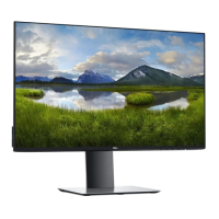
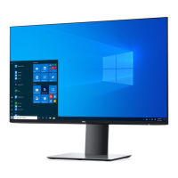
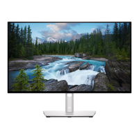
The DELL U2421E is a display monitor, and this manual primarily focuses on its physical construction and the methods required to take it apart. It is built with various internal components, including an LCD panel, interface board, power board, USB board, and a joystick key for navigation. The monitor's design incorporates several fastening methods, such as screws, tapes, and interlocking mechanisms, all of which are addressed in the disassembly process. The internal circuitry manages power distribution, signal processing for display, and connectivity for peripherals via USB. The overall structure is encased within a rear cover and a middle bezel, supported by a stand, and protected during shipping by specific packaging materials.

Usage Features (implied from disassembly):

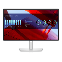
The monitor's design suggests ease of assembly and disassembly for maintenance. For instance, the use of Philips-head screws for most components indicates a standard tool requirement, making it accessible for common repair scenarios. The modular nature of the internal boards (interface board, power board, USB board) implies that individual components can be replaced if faulty, extending the lifespan of the monitor. The presence of a joystick key suggests intuitive user interaction for on-screen display (OSD) navigation, which would be connected to the interface board. The monitor supports various input cables, including DP, USB-C, and USB-A, indicating versatile connectivity options for different devices. The packaging materials, such as the EPE-bag and protective cushion, highlight the care taken to protect the LCD panel during transport and handling, suggesting a robust design for the display itself.

Maintenance Features (explicit and implied):

The manual provides a step-by-step guide for maintenance and repair.

  1. Initial Access: The process begins with opening the carton and removing all accessories and packaging materials, including labels, quick start guides (QSG), Delta-E paper, and various cables (DP, USB-C, USB-A, power cable). This initial step ensures that all necessary items are accounted for and cleared before proceeding to the monitor itself. The base and molded pulp are removed, followed by the monitor and stand, which are then taken out of an EPE-bag and placed on a protective cushion to prevent damage during subsequent steps.
  2. Rear Cover Removal: The rear cover is secured by four Philips-head screws (M4x11). After removing these, the DP cap is also removed. The rear cover is then carefully released by wedging fingers between it and the middle bezel, applying pressure to the middle bezel while pulling up the rear cover, following a specific arrow preference for unlocking mechanisms. This method suggests a combination of screw and snap-fit fasteners. Once lifted, the joystick key cable must be disconnected from the interface board before the rear cover can be fully removed and set aside.
  3. Key Board and USB Board Removal: The key board is secured by two Philips-head screws (M2x2.4) and tapes. These are removed to release the key board. The USB board is secured by one Philips-head screw (M3x6). After removing the screw, the USB FFC cable is disconnected from the interface board, and the USB board unit is removed. This modular design allows for easy replacement of these specific components.
  4. Middle Bezel and LED Components: The LED cable is disconnected from the interface board. The middle bezel is secured by 12 Philips-head screws (M3x5). Once these screws are removed, the middle bezel can be lifted and placed on a cushion foam. Tapes on the back of the middle bezel, which secure the LED cable and LED board, are torn off to release these components. A mylar tape unfixes the panel lamp cable, which is then released from the hooks of the middle bezel. A conductive tape covering the panel lamp connector is torn off, and the panel lamp cable is disconnected from both the panel and the board. These steps highlight the careful handling required for the display's lighting system.
  5. Bracket and Panel Module Separation: Two aluminum foils are torn off, and two Philips-head screws (M3x4) are removed to unlock the bracket from the panel module. The bracket is then moved up, and the earing-lock is pushed to disconnect the LVDS cable from the panel module connectors. The bracket chassis module is then taken away and placed on a protective cushion. This separation is crucial for accessing the main internal boards.
  6. Interface and Power Board Removal: Mylar tape from the hooks of the bracket is removed. Seven Philips-head screws (M4x8 for one, M3x7.5 for six) secure the interface board and power board. After removing these screws, both boards are carefully removed from the bracket chassis module, and all associated cables are disconnected. This allows for individual inspection or replacement of these critical electronic components.
  7. Electrolyte Capacitor Removal (Specific Repair): The manual includes a detailed procedure for removing electrolyte capacitors from printed circuit boards, specifically marked in red. This involves cutting the glue between the bulk cap and the PCB with a knife, ensuring the cutting path is within the glue and does not touch the cap or PCB. The bottom of the bulk cap is cut, and it is pulled up carefully. Finally, the bulk cap pin solder is taken out using a soldering iron and absorber, and the bulk cap is lifted up and away from the PCB. This specialized procedure is indicative of potential common failure points or components requiring specific handling for recycling.

Product Material Information:

The document also lists product material information, categorizing components based on their content and disposal requirements. This section is crucial for proper recycling and environmental compliance. It specifies whether certain substances or components are used in the monitor, such as mercury, batteries, toner, ink, liquids, BFR, asbestos, CFC, HCFC, HFC, HC, gas discharge lamps, and refractory ceramic fibers. It also identifies components requiring selective treatment, such as printed circuit boards (with a surface greater than 10 square cm), LCD displays (greater than 100 cm²), external electric cables, and electrolyte capacitors (height > 25mm, diameter > 25mm). This information ensures that the monitor can be disassembled and its materials sorted according to environmental regulations.

Tools Required:

The necessary tools for disassembly are standard:

  • Screwdriver (Phillips head) #1
  • Screwdriver (Phillips head) #2
  • Penknife
  • Soldering iron and absorber

This comprehensive guide ensures that the DELL U2421E monitor can be effectively disassembled for repair, component replacement, or end-of-life recycling, emphasizing a design that supports maintainability and environmental responsibility.

Dell U2421E Specifications

General IconGeneral
Screen Size24 inches
Resolution1920 x 1200 (WUXGA)
Panel TypeIPS
Aspect Ratio16:10
Refresh Rate60 Hz
Brightness350 cd/m²
Contrast Ratio1000:1
Color Support16.7 million colors
VESA Mount100 x 100 mm
Response Time5 ms (gray to gray)
ConnectivityHDMI, DisplayPort, USB-C, USB Hub
Color Gamut99% sRGB
Viewing Angle178° (horizontal), 178° (vertical)
Weight (with stand)5.6 kg

Related product manuals