Back to Contents Page
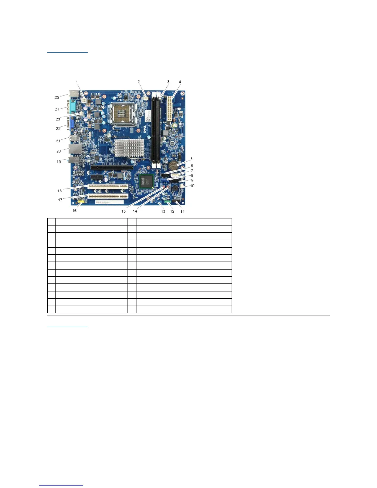
System Board Layout
Dell™Vostro™230ServiceManual—Mini Tower
Back to Contents Page
Processor heat sink/fan assembly power (CPUFAN1)
Memory module connectors (2)
Serial ATA drive connector (SATA3)
Serial ATA drive connector (SATA2)
Serial ATA drive connector (SATA0)
Serial ATA drive connector (SATA1)
Chassis fan connector 2(SYS FAN2)
Power button & LED connector(LEDH1)
Front I/O panel connector (USBF1)
Card reader connector (USBF_INT1)
Password jumper (PW_CLR1)
Audio connector (AUDIOF1)
One LAN and two USB ports
Onboard video connector (VGA)
Chassis fan connector (SYSFAN1)
PS/2 mouse and keyboard connectors