r
D:04:02
^
Fuel Emission and Exhaust System
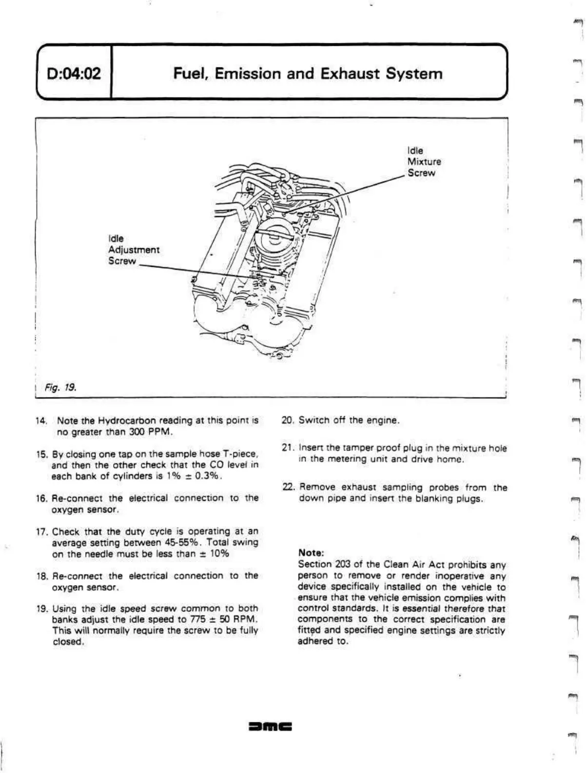
Idle
Adjustment
Screw
Idle
Mixture
Screw
rv,,,.
©~
Fig. 19.
14.
Note the Hydrocarbon reading at this point is
no greater than 300 PPM.
15.
By closing one tap on the sample hose T-piece,
and then the other check that the CO level in
each bank of cylinders is 1% ± 0.3%.
16.
Re-connect the electrical connection to the
oxygen sensor.
17.
Check that the duty cycle is operating at an
average setting between
45-55%.
Total swing
on the needle must be less than ± 10%
18.
Re-connect the electrical connection to the
oxygen sensor.
19.
Using the idle speed screw common to both
banks adjust the idle speed to 775 ± 50 RPM.
This will normally require the screw to be fully
closed.
20.
Switch off the engine.
21.
Insert the tamper proof plug in the mixture hole
in the metering unit and drive home.
22.
Remove exhaust sampling probes from the
down pipe and insert the blanking plugs.
Note:
Section 203 of the Clean Air Act prohibits any
person to remove or render inoperative any
device specifically installed on the vehicle to
ensure that the vehicle emission complies with
control standards. It is essential therefore that
components to the correct specification are
fitted and specified engine settings are strictly
adhered to.
f •"(
 Loading...
