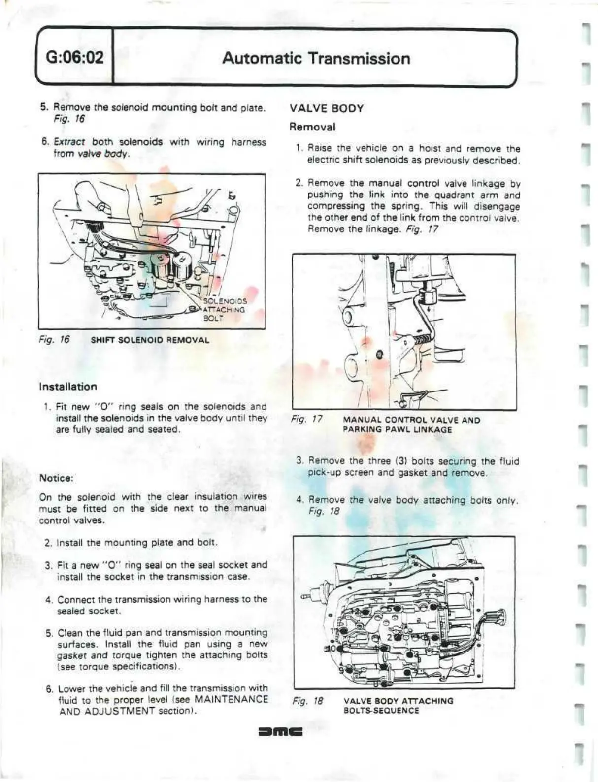
5. Remove the solenoid mounting bolt and plate.
Fig. 16
6. Extract both solenoids with wiring harness
from valve
body.
V^
SOLENOIDS
{£&
ATTACHING
30LT
Fig. 16 SHIFT SOLENOID REMOVAL
Installation
1.
Fit new "0" ring seals on the solenoids and
install the solenoids in the valve body until they
are fully sealed and seated.
VALVE BODY
Removal
1.
Raise the vehicle on a hoist and remove the
electric shift solenoids as previously described.
2.
Remove the manual control valve linkage by
pushing the link into the quadrant arm and
compressing the spring. This will disengage
the other end of the link from the control valve.
Remove the linkage. Fig. 17
Fig. 17 MANUAL CONTROL VALVE AND
PARKING PAWL LINKAGE
Notice:
On the solenoid with the
dear
insulation wires
must be fitted on the side next to the manual
control valves.
2.
Install the mounting plate and bolt.
3. Fit a new "0" ring seal on the seal socket and
install the socket in the transmission case.
4.
Connect the transmission wiring harness to the
sealed socket.
5. Clean the fluid pan and transmission mounting
surfaces. Install the fluid pan using a new
gasket and torque tighten the attaching bolts
(see torque specifications).
6. Lower the vehicle and fill the transmission with
fluid to the proper level (see MAINTENANCE
AND ADJUSTMENT section).
3. Remove the three (3) bolts securing the fluid
pick-up screen and gasket and remove.
4.
Remove the valve body attaching bolts only.
Fig. 18
Fig. 18 VALVE BODY ATTACHING
BOLTS-SEQUENCE
"
 Loading...
