G:06:04
Automatic Transmission
8. Remove the bolts securing the multiple switch
and remove the switch.
9. Disconnect the governor control cable from
the governor computer.
10.
Remove the bolts securing the governor
computer to the case and extract the governor
drive gear and assembly. Fig. 21
Fig. 21. GOVERNOR COMPUTER ASSEMBLY
REMOVAL
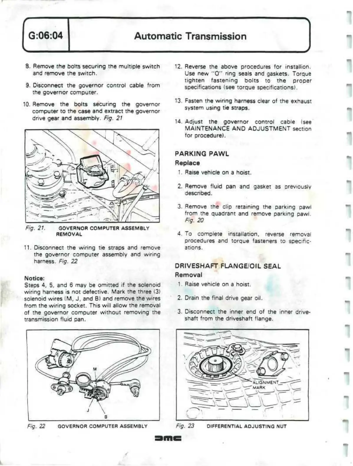
11.
Disconnect the wiring tie straps and remove
the governor computer assembly and wiring
harness. Fig. 22
Notice:
Steps 4, 5, and 6 may be omitted if the solenoid
wiring harness is not defective. Mark the three (3)
solenoid wires (M, J, and B) and remove the wires
from the wiring socket. This will allow the removal
of the governor computer without removing the
transmission fluid pan.
12.
Reverse the above procedures for installion.
Use new "0" ring seals and gaskets. Torque
tighten fastening bolts to the proper
specifications (see torque specifications).
13.
Fasten the wiring harness clear of the exhaust
system using tie straps.
14.
Adjust the governor control cable
(see
MAINTENANCE AND ADJUSTMENT section
for procedure).
PARKING PAWL
Replace
1.
Raise vehicle on a hoist.
2.
Remove fluid pan and gasket as previously
described.
3. Remove the clip retaining the parking pawi
from the quadrant and remove parking pawl.
Fig. 20
4.
To complete installation, reverse removal
procedures and torque fasteners to specific-
ations.
DRIVESHAFT
FLANGE/OIL SEAL
Removal
1.
Raise vehicle on a hoist.
2.
Drain the final drive gear oil.
3. Disconnect the inner end of the inner drive-
shaft from the driveshaft flange.
Fig. 22 GOVERNOR COMPUTER ASSEMBLY Fig. 23 DIFFERENTIAL ADJUSTING NUT
''
 Loading...
