G:07:04
Automatic Transmission
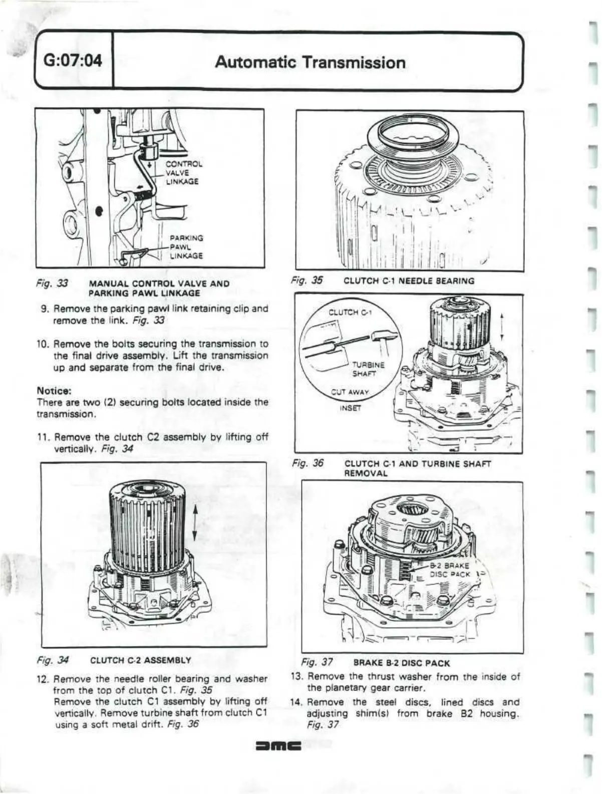
Fig. 33 MANUAL CONTROL VALVE AND
PARKING PAWL LINKAGE
9. Remove the parking pawl link retaining clip and
remove the link. Fig. 33
10.
Remove the bolts securing the transmission to
the final drive assembly. Lift the transmission
up and separate from the final drive.
Notice:
There are two (2) securing bolts located inside the
transmission.
11.
Remove the clutch C2 assembly by lifting off
vertically. Fig. 34
Remove the needle roller bearing and washer
from the top of clutch C1. Fig. 35
Remove the clutch C1 assembly by lifting off
vertically. Remove turbine shaft from clutch C1
using a soft metal drift. Fig. 36
Fig. 35 CLUTCH C-1 NEEDLE BEARING
«d1
3
Fig. 36 CLUTCH C-1 AND TURBINE SHAFT
REMOVAL
Fig. 37 BRAKE B-2 DISC PACK
13.
Remove the thrust washer from the inside of
the planetary gear carrier.
14.
Remove the steel discs, lined discs and
adjusting shim(s) from brake B2 housing.
Fig. 37
 Loading...
