Automatic Transmission
G:07:05
fT<-~*(
Notice:
All of the transmission components except the
planetary gear carrier, have been separated from
the final drive unit.
Notice:
If
it is necessary to repair or replace the planetary
gear carrier, refer to the final drive COMPONENT
REPAIR section for further instructions.
Notice:
If transmission repairs are required, refer to the
TRANSMISSION DISASSEMBLY and
COMPONENT REPAIR sections for further
dismantling instructions.
Notice:
If
final drive repairs are required, refer to the FINAL
DRIVE DISASSEMBLY and COMPONENT
REPAIR sections for further dismantling
instructions.
UNIT REASSEMBLY
1.
Check and adjust the operating clearance on
brake B2.
When the transmission and final drive units are
assembled together, there must be a proper
amount of clearance between the B2 apply piston
and the last brake disc to allow the brake B2 to
function correctly.
The B2 apply piston is located in the transmission
case and the brake discs are located in the final
drive case; therefore, it is necessary to perform the
following measurements on each unit to determine
the amount of clearance that will exist when the
two units are bolted together.
a. Install the B2 disc pack on the planet wheel
carrier as follows:
Fit the shim(s) that were
removed,
a steel disc,
a lined disc, a steel disc and so on. Substitute
the wave disc with a flat disc and fit on the
pack last to obtain exact measurement.
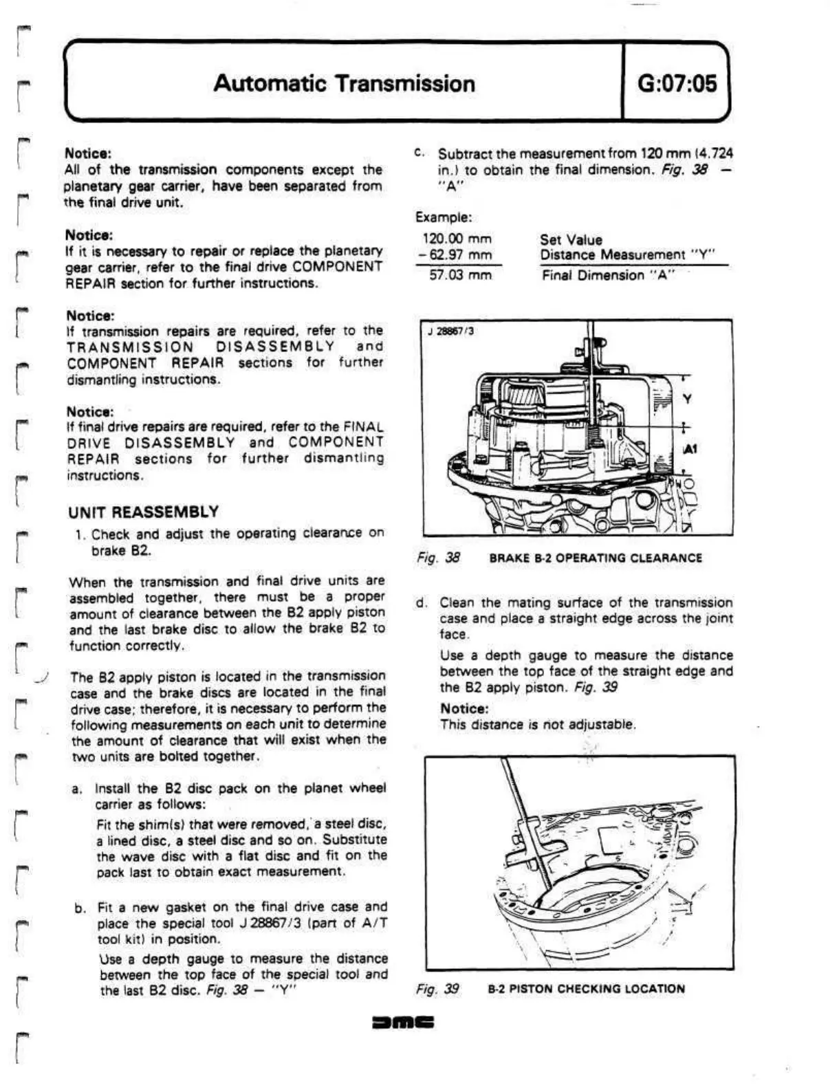
b. Fit a new gasket on the final drive case and
place the special tool J 28867/3 (part of A/T
tool kit) in position.
Use a depth gauge to measure the distance
between the top face of the special tool and
the last B2 disc. Fig. 38 - "Y"
c
-
Subtract the measurement from 120 mm (4.724
in.) to obtain the final dimension. Fig. 38 —
"A"
Example:
120.00 mm
- 62.97 mm
57.03 mm
Set Value
Distance Measurement "Y"
Final Dimension "A"
Fig. 38 BRAKE B-2 OPERATING CLEARANCE
d.
Clean the mating surface of the transmission
case and place a straight edge across the joint
face.
Use a depth gauge to measure the distance
between the top face of the straight edge and
the B2 apply piston. Fig. 39
Notice:
This distance is not adjustable.
Fig. 39 B-2 PISTON CHECKING LOCATION
 Loading...
