Use a micrometer to measure the thickness of
the straight edge used in the above measure-
ment.
Subtract this measurement from the distance
measure obtained in Step "d" to determine the
final dimension "B". Fig. 40
Example:
65.10 mm
-6.38
mm
58.72 mm
Distance Measurement
Thickness of Straight Edge
Final Dimension "B"
M
w
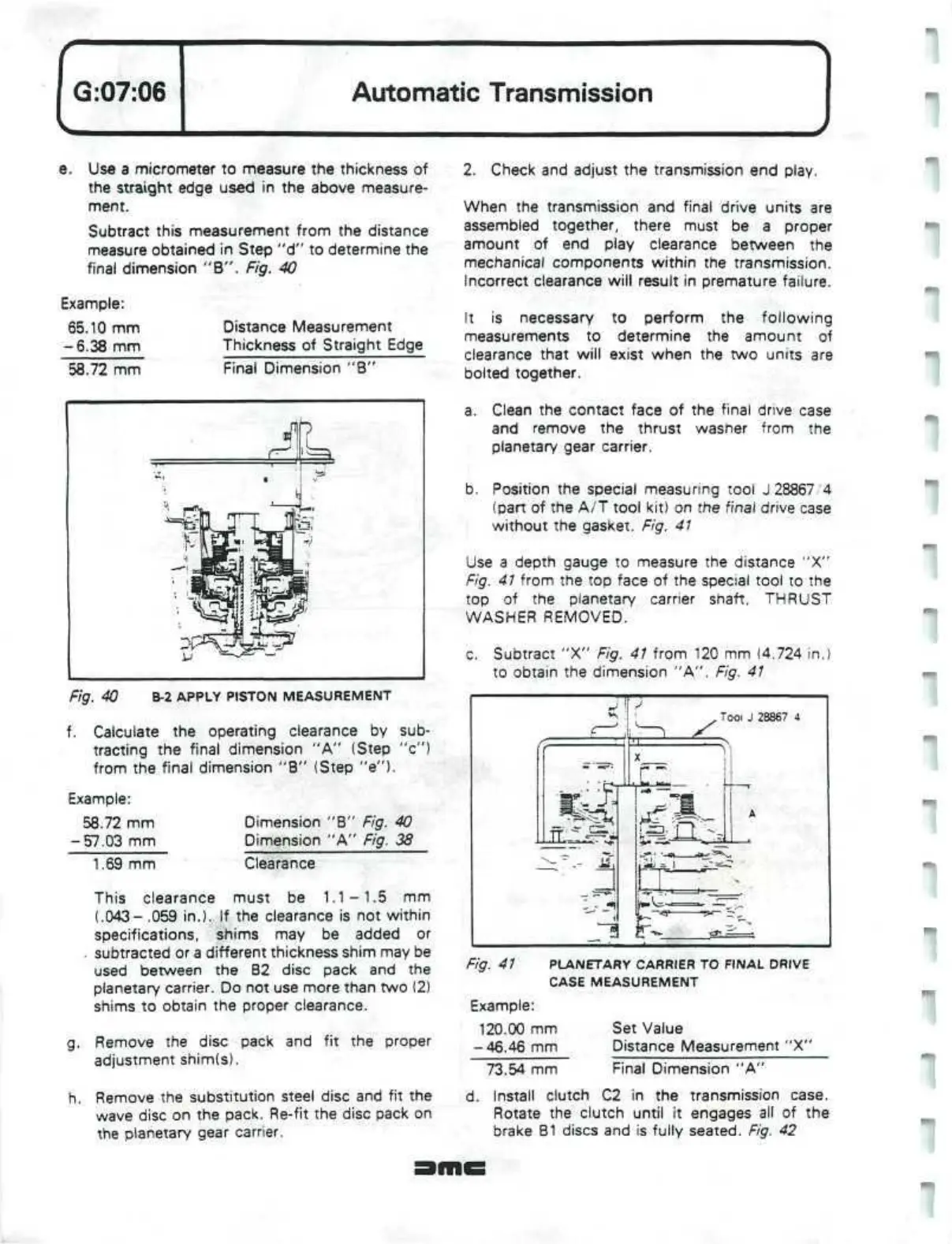
Fig. 40
B-2
APPLY PISTON MEASUREMENT
f. Calculate the operating clearance by sub-
tracting the final dimension "A" (Step "c")
from the final dimension "B" (Step "e").
Example:
58.72 mm
-57.03 mm
1.69 mm
Dimension "B" Fig. 40
Dimension "A" Fig. 38
Clearance
This clearance must be
1.1-1.5
mm
(.043- .059 in.). If the clearance is not within
specifications, shims may be added or
subtracted or
a
different thickness shim may be
used between the B2 disc pack and the
planetary carrier. Do not use more than two (2)
shims to obtain the proper clearance.
g.
Remove the disc pack and fit the proper
adjustment shim(s).
h. Remove the substitution steel disc and fit the
wave disc on the pack. Re-fit the disc pack on
the planetary gear carrier.
2.
Check and adjust the transmission end play.
When the transmission and final drive units are
assembled together, there must be a proper
amount of end play clearance between the
mechanical components within the transmission.
Incorrect clearance will result in premature failure.
It is necessary to perform the following
measurements to determine the amount of
clearance that will exist when the two units are
bolted together.
a. Clean the contact face of the final drive case
and remove the thrust washer from the
planetary gear carrier.
b. Position the special measuring tool J
28867'4
(part of the A/T tool kit) on the final drive case
without the gasket. Fig.
41
Use a depth gauge to measure the distance "X"
Fig. 41 from the top face of the special tool to the
top of the planetary carrier shaft, THRUST
WASHER REMOVED.
c. Subtract "X" Fig.
41
from 120 mm (4.724 in.)
to obtain the dimension "A". Fig. 41
Tooi
J 28867 4
Fig. 41 PLANETARY CARRIER TO FINAL DRIVE
CASE MEASUREMENT
Example:
120.00 mm
-46.46 mm
73.54 mm
Set Value
Distance Measurement "X"
Final Dimension "A"
d.
Install clutch C2 in the transmission case.
Rotate the clutch until it engages all of the
brake B1 discs and is fully seated. Fig. 42
 Loading...
