r
v
Automatic Transmission
A
G:0§:01
*
FINAL DRIVE UNIT
FINAL DRIVE DISASSEMBLY
Notice:
Perform the
transmission/final
drive unit separ-
ation procedure before starting with final drive
assembly.
1.
Remove the governor computer and drive gear
from the case.
2.
Remove the torque converter housing. Fig. 66
3. Remove the bolts securing
t^e,planetary
gear
carrier housing to the case and remove the
carrier assembly and gasket. Fig. 67
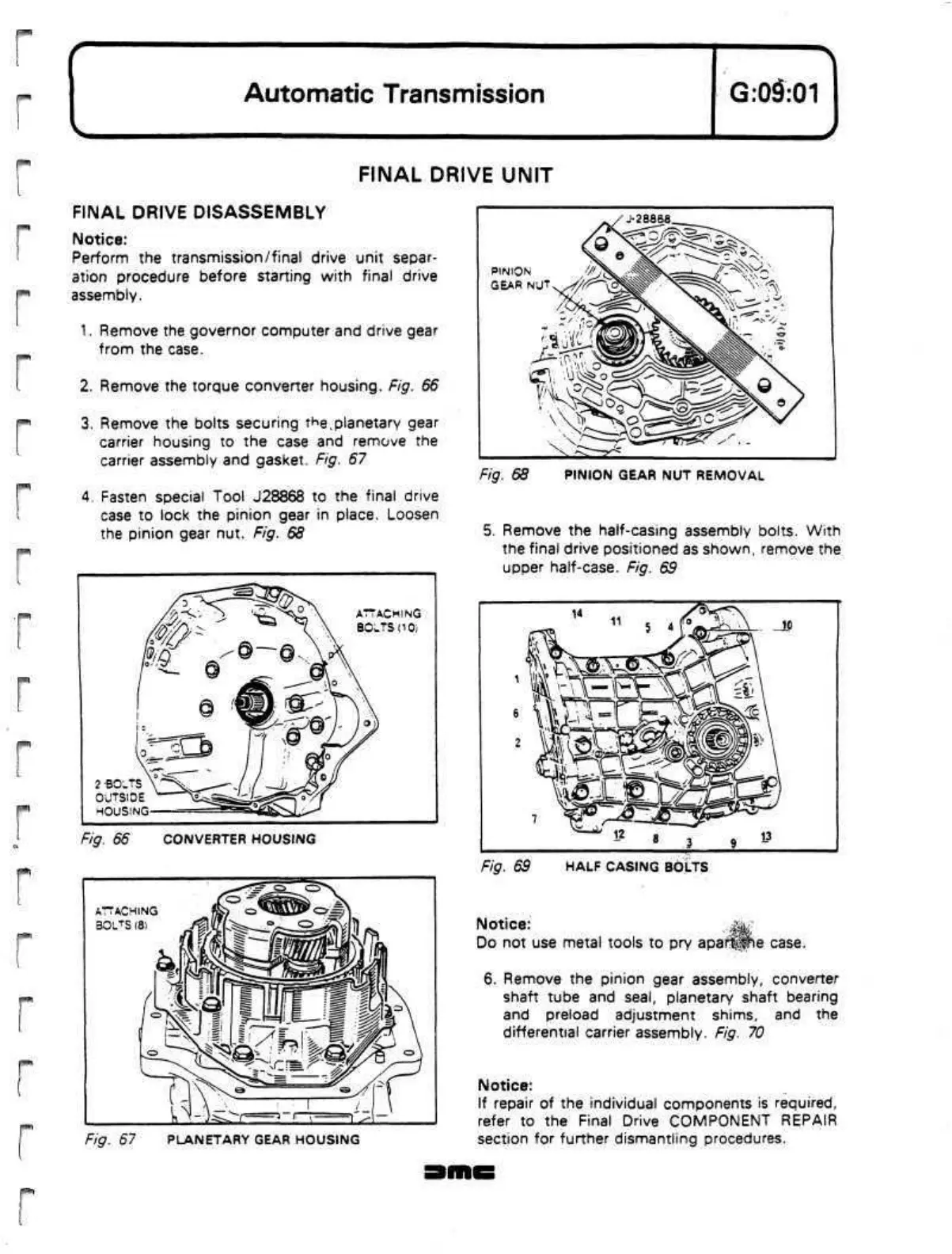
4.
Fasten special Tool J28868 to the final drive
case to lock the pinion gear in place. Loosen
the pinion gear nut. Fig. 68
2 BOLTS
OUTSIDE
HOUSING
Fig. 66 CONVERTER HOUSING
ATTACHING
BOLTS (8)
/fl'i
Fig. 67 PLANETARY GEAR HOUSING
•28868
PINION
GEAR NUT
Fig. 68 PINION GEAR NUT REMOVAL
5. Remove the half-casing assembly bolts. With
the final drive positioned as shown, remove the
upper
half-case.
Fig. 69
Fig. 69 HALF CASING BOLTS
Notice:
.^gagf
Do not use metal tools to pry
apaf^Jie
case.
6. Remove the pinion gear assembly, converter
shaft tube and
seal,
planetary shaft bearing
and preload adjustment shims, and the
differential carrier assembly. Fig. 70
Notice:
If repair of the individual components is required,
refer to the Final Drive COMPONENT REPAIR
section for further dismantling procedures.
 Loading...
