I
r
r
r
r
r
r
r
r
r
r
r
r
r
r
r
r
r
DIAGNOSTIC SOCKET
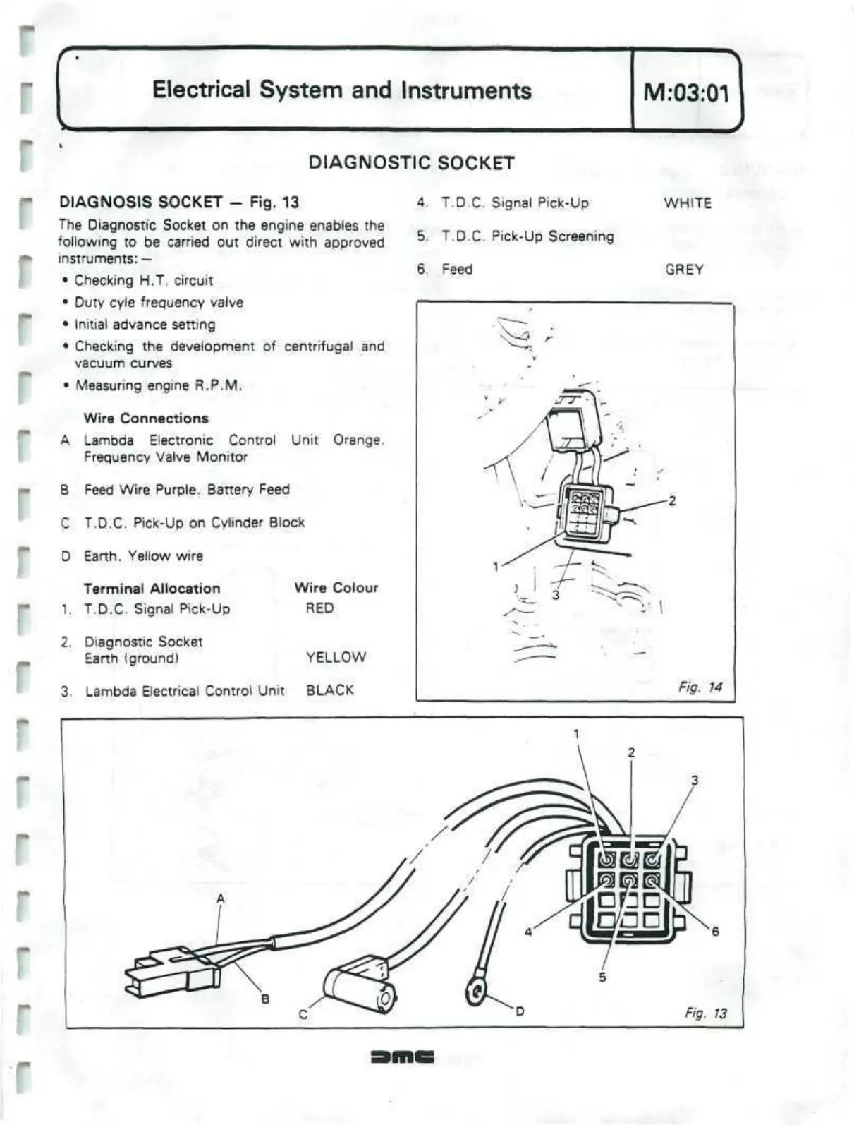
DIAGNOSIS SOCKET
-
Fig. 13
The Diagnostic Socket on the engine enables the
following to be carried out direct with approved
instruments:
—
• Checking H.T. circuit
• Duty
cyle
frequency valve
• Initial advance setting
• Checking the development of centrifugal and
vacuum curves
• Measuring engine R.P.M.
Wire Connections
A Lambda Electronic Control Unit Orange.
Frequency Valve Monitor
B Feed Wire Purple. Battery Feed
C T.D.C.
Pick-Up
on Cylinder Block
D Earth. Yellow wire
4.
T.D.C. Signal Pick-Up
5. T.D.C. Pick-Up Screening
6. Feed
WHITE
GREY
Terminal Allocation
1.
T.D.C. Signal Pick-Up
2.
Diagnostic Socket
Earth (ground)
Wire Colour
RED
YELLOW
3. Lambda Electrical Control Unit BLACK