(
1
pT*$
?*m\
Refit:
The anti-emulsion plate
The suction pipe fitted with a new "0" ring seal
A new cork gasket and the sump. (Fig. 87)
Turn engine over.
The crankshaft must be positioned as follows in
order to set the valve timing.
Keyway
vertical
No.
1 piston 15 mm (19/32") down its bore on
the compression stroke (BTDC) to avoid the
risk of contact with the valves.
I
Fig. 88)
nsert the roll pins and push them in until they rest
on the pin punches.
Remove the liner clamps.
Fit the cylinder head gaskets dry.
Fit the cylinder head.
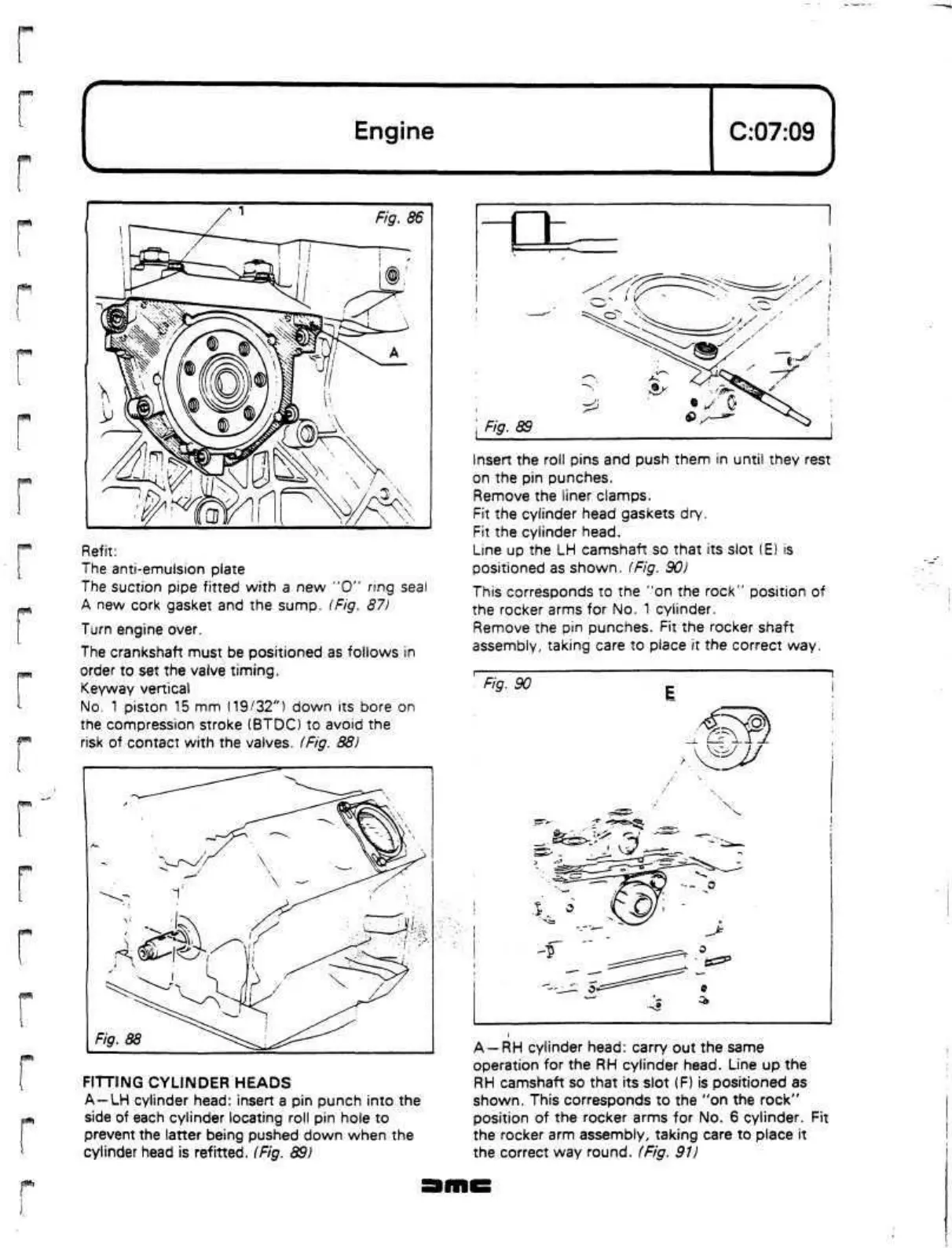
Line up the
LH
camshaft so that its slot
(E)
is
positioned as shown.
(Fig.
90)
This corresponds to the "on the rock" position of
the rocker arms for No. 1 cylinder.
Remove the pin punches. Fit the rocker shaft
assembly, taking care to place it the correct way.
' Fig. 90
Z
|
FITTING CYLINDER HEADS
A—LH
cylinder head: insert a pin punch into the
side of each cylinder locating roll pin hole to
prevent the latter being pushed down when the
cylinder head is refitted. (Fig. 89)
A
—RH
cylinder head: carry out the same
operation for the RH cylinder head. Line up the
RH camshaft so that its slot (F) is positioned as
shown.
This corresponds to the "on the rock"
position of the rocker arms for No. 6 cylinder. Fit
the rocker arm assembly, taking care to place it
the correct way round. (Fig. 91)
 Loading...
