Page 10
Part No. XG0509
DFSP Rio Pedestal Stove
Quality Gas Products by Montigo
Installation
B-Vent
B-Vent Installation
This Rio Stove is certified for use with standard B-Vent, when in-
stalled using Montigo's optional B-Vent Conversion Kit (part # FSTK-
03), and provided the following steps are carefully followed. Stove
Pipe, Liner, and B-Vent are not included with the kit. Refer to Step 5.
When vented with standard 4" B-Vent, the B-Vent is installed directly
onto the draft hood assembly. Covering the B-vent with stove pipe is
optional for this installation. When vented using 4" flex liner, the flex
must be covered with stove pipe.
Refer to the current CAN/CGA B-149.1 and .2 or ANSI Z223.1-1988
Gas Installation Code for B-Vent installation regulations.
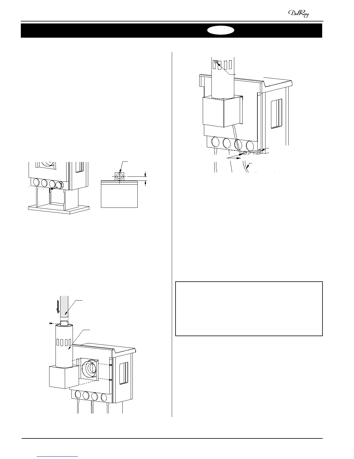
Figure 21. Location of the flue
collar on the draft hood, for
determining the location of
the ceiling opening.
1. There are four relief pots on the back of the stove body. For
B-Vent Installations only, these pots must be removed to provide
adequate combustion air. (See Figure 20.)
2. Check to ensure that the path for venting is clear. Try to position
the stove midway between two joists to avoid having to cut them.
Cut and frame an opening centered over the vent collar on the
draft hood
(see Figure 21).
3. Attach the draft hood assembly to the back of the stove and
secure with four sheet metal screws as shown in Figure 22.
Figure 20. Removing the relief
pots on B-Vent Installa-
tions.
4. Caution: This stove is shipped ready for direct vent installation.
For B-Vent installations, the following wiring change must be
made.
Gently pull the spill switch wires from the bottom of the draft
hood, and splice them into the On/Off switch circuit. The
switch should be wired in series as shown in Figure 23.
5. Montigo offers a complete range of stove pipe and flex liner for
completing the installation. Available components are listed in
Appendix B - Venting Components:
Refer to the installation instructions supplied with the FSTK03 for
more information. When using other brands of stove pipe or liner,
refer to the vent manufacturer's installation instructions.
Test your B-Vent installation after completion to ensure that
no combustible by-products are spilling from the draft hood
opening. This draft test should be performed after a fifteen
(15) minute warm up period. The manufacturer will not be
responsible for any installations with inadequate draw.
CAUTION:
Figure 23. Wiring the draft hood spill switch into the millivolt circuit.
Spill switch
Burner 'On/Off'
switch
To gas valve 'TH'
connections
Splice here
Figure 22. Attaching the draft hood assembly and the first B-Vent
section.
Draft
hood as
sembly
4" B-Vent