DNT-T103 & DNT-T221 Application Guide
Page 10 of 41 Document Edition 4.1
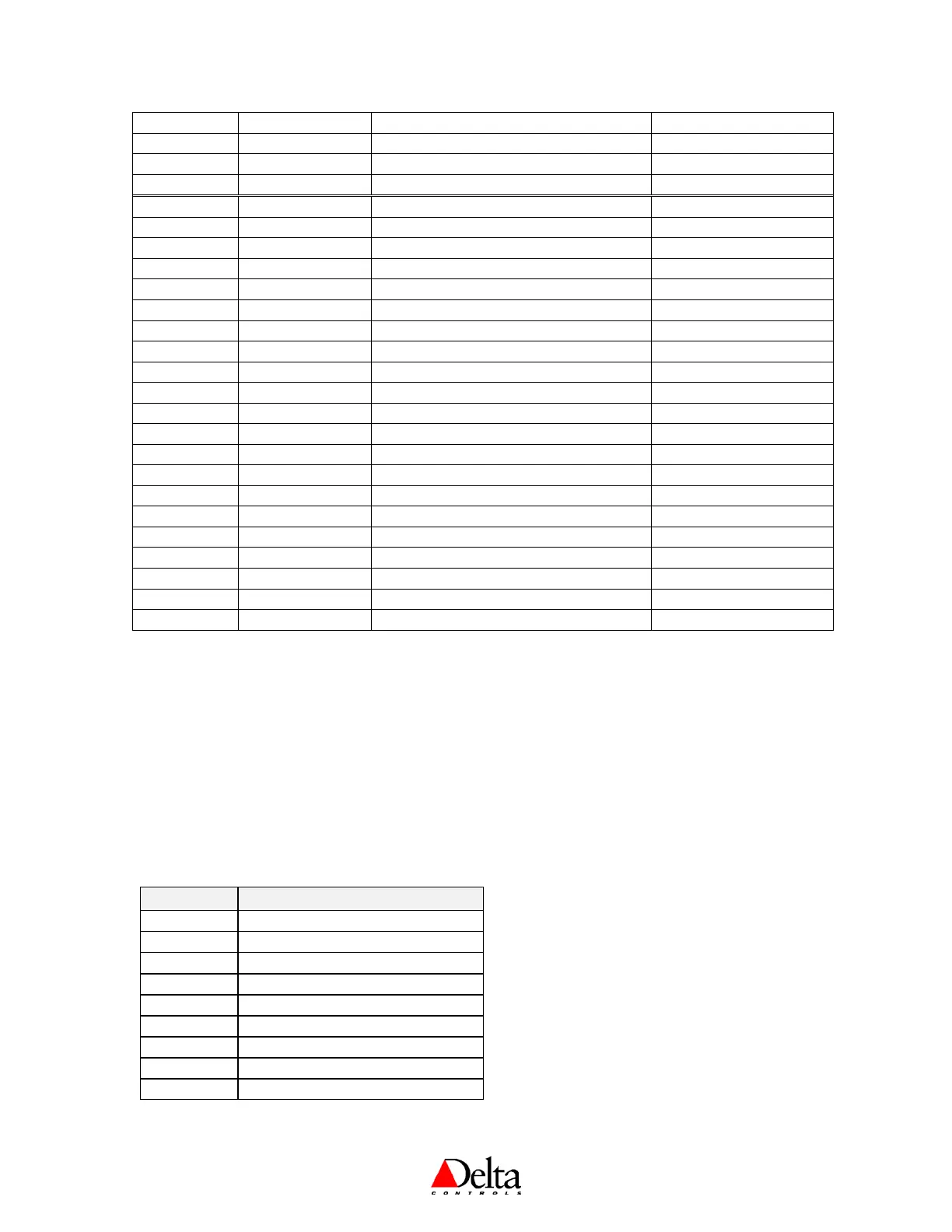
AV11 Night Cool Setpoint Night Setpoint for Cooling ºC = 30; ºF = 86; % = 30
AV12 Application Control Application (Name Changes) None
AV13 Alg Mode Algorithm Mode 0 (OFF or Night)
AV14 Controller Status Status of Internal Control Loop N/A
AV15 Display Code Local Display & Button Handling 1237
AV16 AI1 Calibration Input 1 Calibration (Temperature) 0.0
AV17 AI2 Calibration Input 2 Calibration (MUXed IP) 0.0
AV18 AI3 Calibration Input 3 Calibration (Humidity) 0.0
AV19 Proportional Band Control Loop Tuning Parameter ºC = 1; ºF = 2; % = 10
AV20 Reset Rate Control Loop Tuning Parameter 1.0
AV21 Output 1 Config Output 1 Configuration Variable As per Application Setup
AV22 Output 2 Config Output 2 Configuration Variable As per Application Setup
AV23 Output 3 Config Output 3 Configuration Variable As per Application Setup
AV24 Setup 1 Setup Variable 1 (Name Changes) As required
AV25 Setup 2 Setup Variable 2 (Name Changes) As required
AV26 Setup 3 Setup Variable 3 (Name Changes) As required
AV27 Setup 4 Setup Variable 4 (Name Changes) As required
AV28 Setup 5 Setup Variable 5 (Name Changes) As required
AV29 Setup 6 Setup Variable 6 (Name Changes) As required
AV30 Baud Rate Network Baud Rate *
AV31 PIN PIN (4-Bit Configuration Access Code) 1011
AV32 Service Tool Mode Service Tool Access Disable/Enable (0-2) 1 (or 2 when AV12 = VAV)
AV33 Box Mode Heating & Cooling Modes for VAV/VVT 0 (Cooling)
AV34 System Stats System Statistics N/A
AV35 System Log System Event Log N/A
* Names are user settable (to a maximum of 32 characters), and only on outputs when they are controlled remotely (i.e.,
MUXed).
These are the typical objects that may be commanded on the fly by a user or from GCL++, and also include the Outputs
(AV1-3) when they are MUXed. Never command the Configuration Variables (AV12, AV21-13) on the fly.
System Events and Statistics
System Stats (AV34)
The Description field in this object provides a count of notable events that have occurred. Each
statistic consists of an event code (H- Hardware, C- Communication, S-Service + two-digit code) and
an event count. With the exception of the reset count (H04) and the flash programming count (H05),
event counts are reset on power up. The PresentValue indicates how many different types of events
have occurred since power up.
Code Description
H04 Reset count
H05 Flash programming count
H06 Flash operation failure
H08 I2C communication failure
C01 Communication overflow
C02 Buffer unavailable
C03 Into Sole Master
C04 DNA conflict
C05 MAC address conflict
 Loading...