DNT-T103 & DNT-T221 Application Guide
Page 20 of 41 Document Edition 4.1
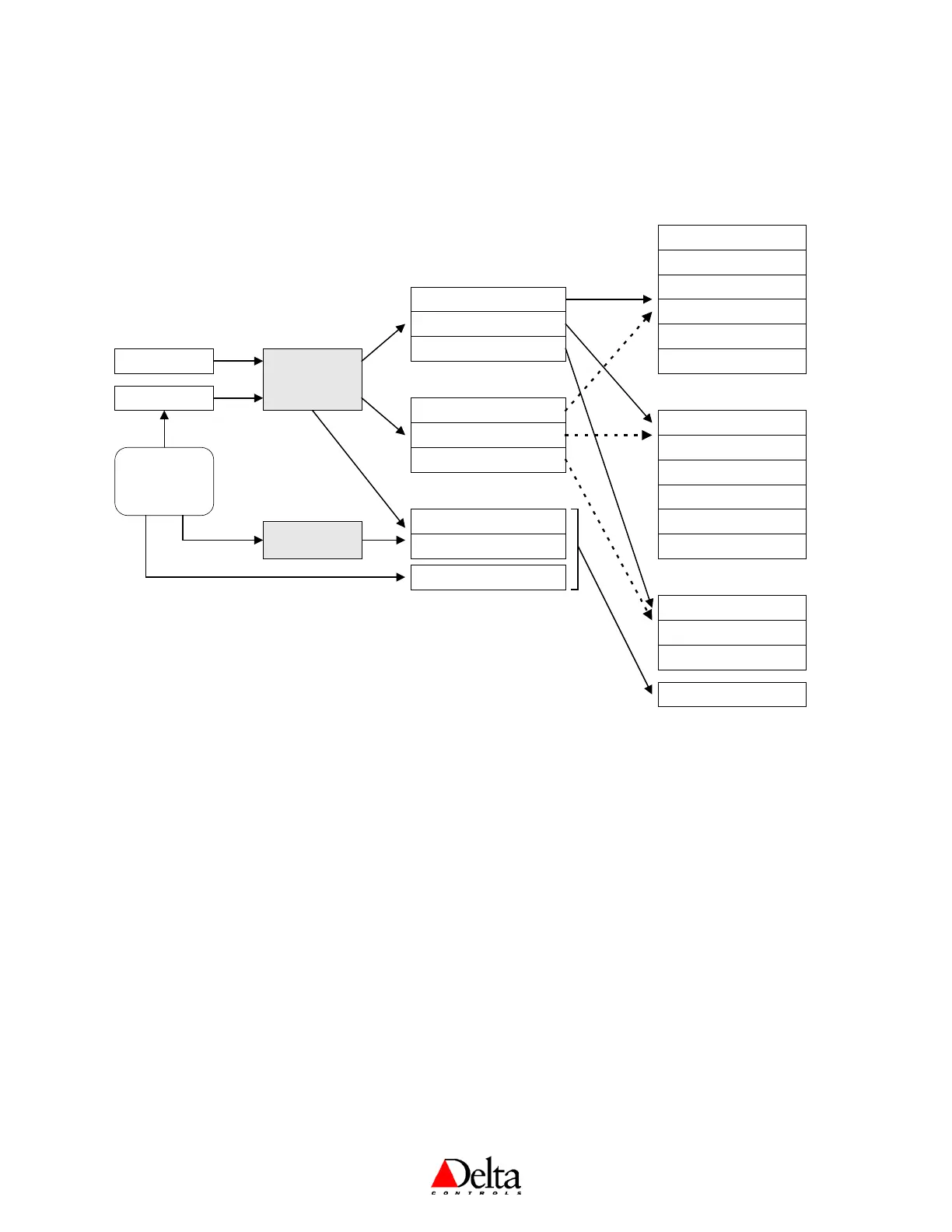
CONTROL DIAGRAM
The following diagram displays occupied mode and helps illustrate the relationship between the
internal software loop controller and various objects, including outputs.
CONTROL APPLICATIONS
1. NONE (or MUX) – [Application (AV12) = 0]
Function: No local control strategy, allowing the outputs (via AV1 to AV3) to be directly controlled
from a remote device.
• Triac outputs may be configured as Binary (which are not delayed; their values are transferred
immediately upon being received), PWM, and Tri-state (on Outputs 1 & 2).
• Analog outputs may be configured for 0-10v actuators (DNT-T221 only).
• Outputs configured as Pulse Width Modulation require that their “Low” and “High” variables be
appropriately configured for the particular type of device the outputs are connected to. Default
values of 59 and 293 are suitable for Belimo PWM actuators (representing 0.59 and 2.93 seconds
respectively).
Controller &
Sequencing
Input (AI1)
Setpoint (AV6)
Binary (Dir or Rev)
PWM (Dir or Rev)
Analog (Dir or Rev)
Analog VAV Flow Damper
Tri-State Actuator
Tri-State VAV Flow Damper
Heating Stage 1 (H1)
Heating Stage 2 (H2)
Heating Stage 3 (H3)
Cooling Stage 1 (C1)
Cooling Stage 2 (C2)
Cooling Stage 3 (C3)
Constant Fan Operation (C)
Intermittent Fan Operation (I)
Manual Fan Operation (M)
Output 1
Output 2
Binary (Dir or Rev)
PWM (Dir or Rev)
Time Proportioned (D or R)
Analog (Dir or Rev)
Tri-State Actuator
Tri-State VAV Flow Damper
Output 3
Binary (Dir or Rev)
PWM (Dir or Rev)
Time Proportioned (D or R)
Cooling
Heating
Fan
Algorithm Mode
(AV13)
BACstat Buttons
(or remote
command via
GCL or OWS)
Notes:
1. ∗ indicates the output type is only applicable for the DNT-T103.
2. ∗ ∗ indicates the output type is only applicable for the DNT-T221.
3. An analog output type for outputs 1 & 2 on a DNT-T221 when HPU has been
selected provides a 0 or 10v signal - it is not a 0 to 10v signal nor a dry contact.
4. The output functions and types that are available are dependent on the control
application selected and what was selected for the previous output.
5. This is not a comprehensive diagram and does not include all output functions.
Refer to Output Functions and Types later in this document.
Binary Fan (On/Off)