Document Edition 4.1 Page 1 of 41
PPLICATION
UIDE
Delta Network Thermostat: BACstat II
DNT-T103 & DNT-T221
Document Edition 4.1
Product Description
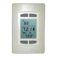
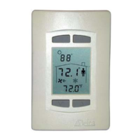
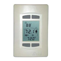
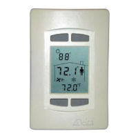
The DNT-T103 and the DNT-T221 are intelligent room thermostats with
custom 3-value, 96 segment, LCD displays. The DNT products can
communicate directly on a BACnet MS/TP network or Delta’s proprietary
LINKnet network.
They are capable of displaying a wide-range of digital or analog values,
including setpoints, temperature, air flow, heating and cooling status, fan
speed, valve and damper position, and more. When connected on a BACnet
MS/TP network the DNT-T103 and T221 function as independent BACnet
thermostats. When connected to a Controller on a LINKnet network they
provide programmable remote sensor and expanded I/O capabilities. This
version’s firmware can be flash loaded over the network, and have
termination resistors that are jumper selectable.
The DNT-T103 has 1 extra input, 3 binary outputs and a number of built-in application control strategies. The
DNT-T221 has 2 extra inputs, 2 analog and 1 binary output and built-in application control strategies. As a
result, these BACstats are capable of stand-alone control when directly connected on an MS/TP network.
Contents
OTHER RELEVANT DOCUMENTS .................................................................................................. 2
IMPORTANT
INFORMATION .......................................................................................................... 2
SETUP
& CONFIGURATION ............................................................................................................. 2
NETWORK COMMUNICATIONS ........................................................................................................... 2
D
EVICE CONFIGURATION (KEYPAD) .................................................................................................. 2
SERVICE TOOL MODE (KEYPAD) ....................................................................................................... 7
I
NPUT CALIBRATION .......................................................................................................................... 8
I
NPUT SCALE RANGES ...................................................................................................................... 8
SOFTWARE
& PROGRAMMING...................................................................................................... 9
OBJECTS............................................................................................................................................ 9
PROGRAMMING ............................................................................................................................... 12
CONTROL
FUNCTIONS ................................................................................................................... 12
O
VERVIEW ...................................................................................................................................... 12
SOFTWARE LOOP CONTROLLER ....................................................................................................... 15
SETPOINTS ...................................................................................................................................... 18
C
ONTROL DIAGRAM ........................................................................................................................ 19
CONTROL APPLICATIONS (MUX, VAV, VVT, HPU, FCU, RAD, HUM) ............................................ 20
O
UTP UT FUNCTIONS & TYPES ......................................................................................................... 28
OWS
FUNCTIONS .............................................................................................................................. 33
A
PPENDIX A: PROGRAMMING NOTES .................................................................................................... 31
A
PPENDIX B: LINKNET ......................................................................................................................... 32